A cable passing fire door structure used in an integrated pipe corridor

A technology of integrated pipe gallery and fire door, applied in underwater structures, infrastructure engineering, electrical components, etc., can solve the problems of waste, deviation, damage to fire partition walls, etc., and achieve the effect of improving efficiency and convenient laying.

Pending Publication Date: 2019-01-11
上海水业设计工程有限公司
View PDF0 Cites 0 Cited by
  • Summary
  • Abstract
  • Description
  • Claims
  • Application Information

AI Technical Summary

Problems solved by technology

[0004] The invention aims to solve the problem of deviation caused by laying cables along the reserved holes or the waste caused by the way of destroying fire partit

Method used


Image

  • A cable passing fire door structure used in an integrated pipe corridor
  • A cable passing fire door structure used in an integrated pipe corridor
  • A cable passing fire door structure used in an integrated pipe corridor

Examples


Example Embodiment

[0024] The present invention will be further described in detail below through specific embodiments in conjunction with the accompanying drawings. It should be noted here that the descriptions of these embodiments are used to help the understanding of the present invention, but do not constitute a limitation of the present invention. In addition, the technical features involved in the various embodiments of the present invention described below can be combined with each other as long as they do not conflict with each other.

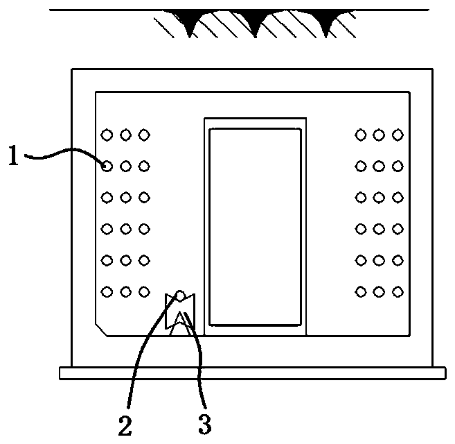
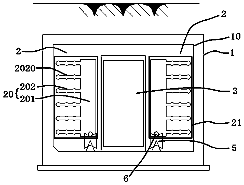
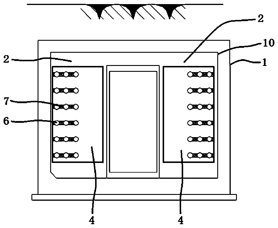
[0025] See Figures 2 to 4 , what is shown in the figure is a kind of cable passing fire door structure used in the integrated pipe gallery.

[0026] The cable passing fire door structure is mainly composed of integrated pipe gallery 1, side partition walls 2, middle fire doors 3 and side fire doors 4 and other components.

[0027] The integrated pipe gallery 1 is formed under the ground. A power cable cabin 10 or other functional cabins are formed inside


PUM


Abstract

The invention discloses a cable passing fire door structure used in a comprehensive pipe corridor, comprising a comprehensive pipe corridor, wherein a power cable cabin is formed inside the comprehensive pipe corridor; Side partition walls respectively arranged on the left and right sides of the power cable cabin, wherein partition wall reserved holes are formed on the side partition walls; a sidefire panel disposed in front of and/or behind the side partition wall, the side fire panel covering at least the hole main path portion in the side partition wall; and an intermediate fire door disposed inside the power cable compartment and between the side partitions on the left and right sides. The invention has the beneficial effects that the influence of destroying the partition wall duringconstruction and installation is basically eliminated by adding the side partition wall and the side fireproof board, so that the laying of the power cable is more convenient and the benefit is improved.

Description


Claims


Application Information

Patent Timeline
Owner 上海水业设计工程有限公司
Why Eureka
Try Eureka