A stainless steel positioning shaft for high-speed railways

A stainless steel and positioning shaft technology, applied in the direction of overhead lines, etc., can solve the problems of low strength and corrosion resistance that cannot be compared with stainless steel, and achieve the effects of small bearing area, superior performance, and excellent plasticity and toughness

Inactive Publication Date: 2019-01-15
XIAN FUBANG TECH INDAL
View PDF0 Cites 0 Cited by
  • Summary
  • Abstract
  • Description
  • Claims
  • Application Information

AI Technical Summary

Problems solved by technology

The current carbon steel or aluminum alloy ZJ positioners need to improve their corrosion resistance through surface treatment during the manufacturing process. The former is mainly galvanized, while the latter is anodized, but even after surface treatment, the corrosion resistance of the two remains the same. Can not be compared with stainless steel, its strength is also lower than ASME201 and 2205 duplex stainless steel

Method used


Image

  • A stainless steel positioning shaft for high-speed railways
  • A stainless steel positioning shaft for high-speed railways

Examples


Example Embodiment

[0014] The present invention will be further described in detail below in conjunction with the drawings:

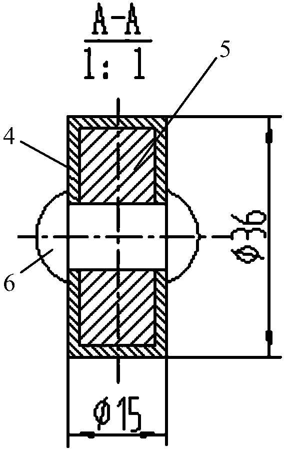
[0015] See figure 1 with figure 2 , The stainless steel positioning shaft for high-speed rail of the present invention includes a rod-shaped stainless steel body 1, at both ends of the rod-shaped stainless steel body 1, one end is fixedly connected with a stainless steel hook body 2, and the other end is fixedly connected with a stainless steel shaft 3; The middle of 1 is bent downward at an angle of 100 degrees. The stainless steel shaft 3 is arranged vertically downward in the axial direction; the stainless steel shaft 3 is a rectangular connecting sleeve 4 at the end connected to the rod-shaped stainless steel body 1, and the rod-shaped stainless steel body 1 is at the end connected to the stainless steel shaft 3. To be able to insert the rectangular end 5 of the rectangular connecting sleeve 4; the rectangular end 5 of the rectangular connecting sleeve 4 is fixed by stain


PUM


Abstract

The invention relates to a stainless steel positioning shaft for high-speed railways, comprising a rod-shaped stainless steel body, wherein, at two ends of the rod-shaped stainless steel body, a stainless steel hook body is fixedly connected at one end and a stainless steel rotating shaft is fixedly connected at the other end; the center of the rod-shaped stainless steel body is bent down by an angle of 100 degrees. According to the strength of the stainless steel member, the positioner with smaller bearing area can be designed through structural optimization.

Description


Claims


Application Information

Patent Timeline
Owner XIAN FUBANG TECH INDAL
Why Eureka
Try Eureka