Frame type rail weighing sensor

A load cell and frame-type technology, applied in the field of rail weighing, can solve problems such as increasing equipment cost, and achieve the effect of reducing equipment cost, shortening length, and reducing installation height

Pending Publication Date: 2019-01-15
BEIJING HUAHENG NEW TECH DEV +1
View PDF0 Cites 2 Cited by
  • Summary
  • Abstract
  • Description
  • Claims
  • Application Information

AI Technical Summary

Benefits of technology

This new design allows for an improved weight measuring system called a frame type or weldable rail (FRA) scale sensors. These systems have built into them's frames without any holes left open during manufacture. They also include a U shaped cavity inside where they are supported instead of just one long rod like traditional scales. By adding this features, these devices can be more efficient at detecting loads placed along rails than previous methods due to their shorter distance from the main body of the structure being measured. Additionally, there may exist other components such as a spring mechanism attached to the FRA itself, reducing its overall size while still providing enough strength against bending forces caused by heavy traffic over it. Overall, these improvements make the measurement process faster and easier compared to older ways.

Problems solved by technology

This patented technical problem addressed in this patents relates to improving the efficiency at detecting excessive loads caused by train movements during high speeds or heavily loaded conditions without adding extra components like pads that increase costs.

Method used


Image

  • Frame type rail weighing sensor
  • Frame type rail weighing sensor
  • Frame type rail weighing sensor

Examples


Embodiment Construction

[0027] The following will clearly and completely describe the technical solutions in the embodiments of the present invention with reference to the accompanying drawings in the embodiments of the present invention. Obviously, the described embodiments are only some, not all, embodiments of the present invention. Based on the embodiments of the present invention, all other embodiments obtained by persons of ordinary skill in the art without making creative efforts belong to the protection scope of the present invention.

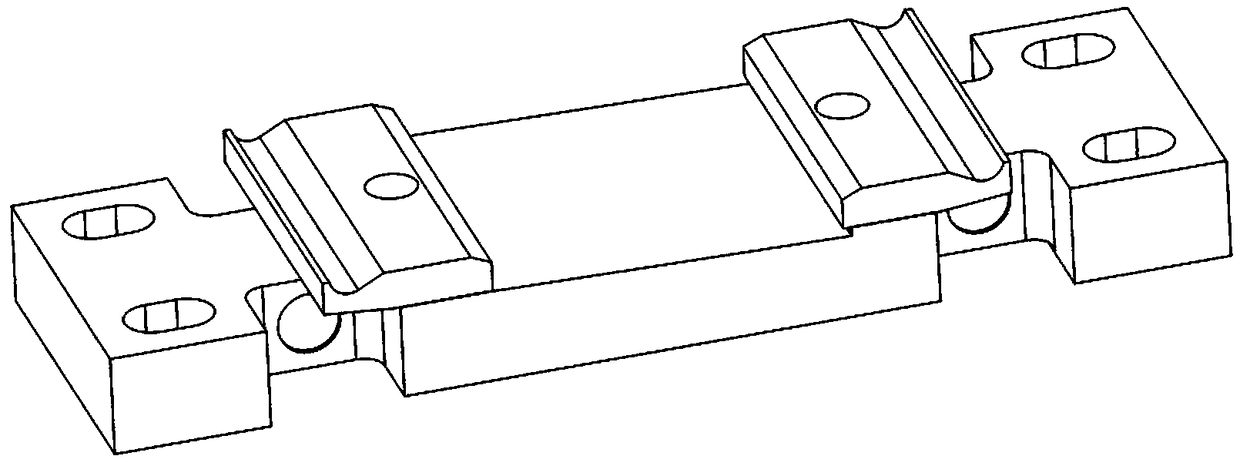
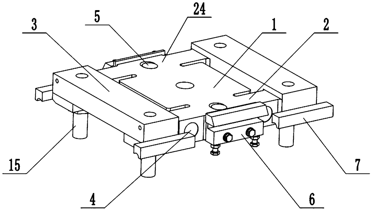
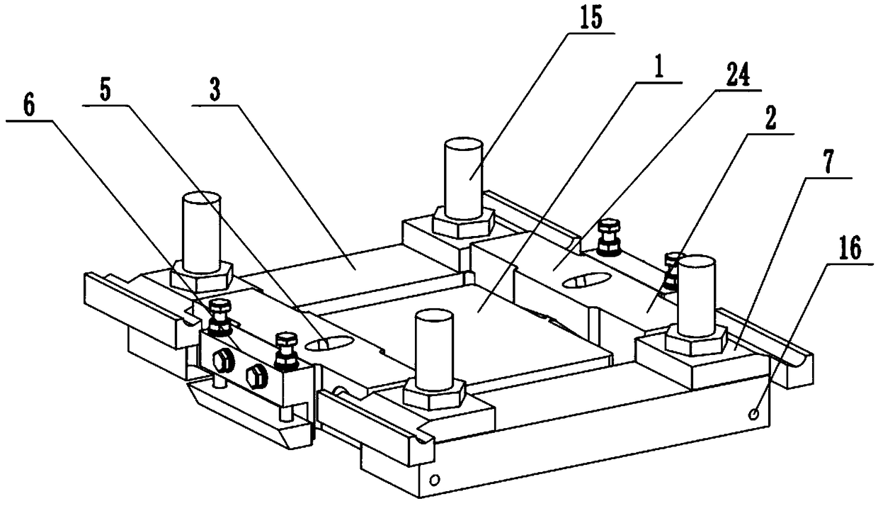
[0028] The purpose of the present invention is to provide a frame-type track load cell to solve the above-mentioned problems in the prior art, without customizing a special sleeper, and making the stress state of the sleeper closer to that of a general sleeper.

[0029] In order to make the above objects, features and advantages of the present invention more comprehensible, the present invention will be further described in detail below in conjunction with the acc


PUM


Abstract

The invention discloses a frame type rail weighing sensor. The frame type rail weighing sensor comprises a support, strain beams and a bearing beam, wherein the support comprises a support main body;side supports are symmetrically arranged on two sides of the support main body; the strain beams are arranged at two ends of the side supports respectively; a strain hole is formed in the side face ofeach strain beam; a mounting hole is formed in each side support; a rail gauge adjusting device is arranged on the outer side of each side support; each bearing beam is positioned at the outer end ofthe corresponding strain beam; the outer ends of the strain beams are connected through the bearing beams respectively; and steel rail baffle plates are arranged at two ends of the upper plane of each bearing beam. According to the frame type rail weighing sensor, the space between the steel rails and prestressed concrete sleepers is utilized efficiently and effectively, a special sleeper does not need to be used, the equipment cost is reduced, the rail gauge adjusting devices are installed on two sides of the side supports of the sensor for carrying out the adjustment of rail gauges, and lateral force received by the steel rails and the frame type rail weighing sensor is born by shoulders of sleeper rail bearing grooves, so that the strained condition of the sleepers is closer to that ofgeneral sleepers.

Description


Claims


Application Information

Patent Timeline
Owner BEIJING HUAHENG NEW TECH DEV
Why Eureka
Try Eureka