A miniature self-powered device based on bridge-type MPEG
A self-powered, bridge-type technology, applied to piezoelectric effect/electrostrictive or magnetostrictive motors, electrical components, generators/motors, etc., can solve problems such as increasing the risk of use and increasing the cost of medical equipment. Achieve the effect of improving battery life, simple structure and strong practicability
Inactive Publication Date: 2019-01-15
DALIAN MARITIME UNIVERSITY
View PDF2 Cites 0 Cited by
- Summary
- Abstract
- Description
- Claims
- Application Information
AI Technical Summary
Benefits of technology
This patented technology relates to small devices that use pressure waves or electricity from an outside force to provide power without being affected by any changeable factors like temperature or humidity levels during operation. By placing this type of membrane near certain parts of these components, it becomes possible to create multiple types of resonance modes at specific locations within each component's volume. These resonances are then used to produce useful signals through electronic circuits connected thereto. Overall, this technology allows for more reliable and efficient batteries replacing in smaller sensors while maintaining their effectiveness over longer periods of time.
Problems solved by technology
Technologies described in this patents involve developing new types of wireless sensory systems called “wireless mesh” senses". These wirelessly distributed sensors require frequent replacement due to their limited lifetimes. However, they still consume significant amounts of electrical current during regular maintenance procedures. Additionally, some existing wired sensor networks may experience reduced performance over time because of increased wear out rates and decreased reliability issues associated with repeated disconnection/replacement operations.
Method used
View moreImage
Smart ImageViewing Examples

Examples
Embodiment 1
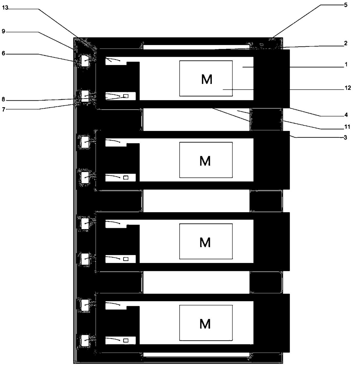
[0054] The size of silicon base 4 is 10x20x0.1mm 3 As an example, the size of the proof mass 12 at one end is 10x10x0.55mm 3 . The size of the active electrode part is 5x8mm 2 . The resonant frequency is 278.5 Hz when the Z-axis acceleration of the miniature self-powered device is 1G, the output voltage is 3.2V under the load resistance of 1Mohm, and the generated power calculated in rms is 1.3μW.
Login to view more PUM
 Abstract
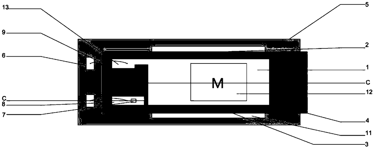
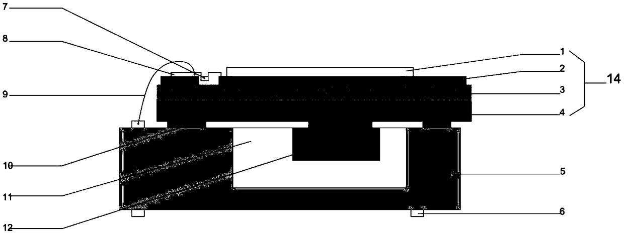
The invention provides a miniature self-powered device based on bridge type MPEG, which is characterized in that the device comprises a piezoelectric structure having a silicon base and a frame coupled to the lower part of the piezoelectric structure through a coupling bridge for accommodating an inspection mass; the piezoelectric structure is coupled to the lower part of the piezoelectric structure through a coupling bridge. The piezoelectric structure includes a silicon substrate, an upper electrode and a lower electrode disposed on the silicon substrate, and a piezoelectric film for generating electric energy sandwiched between the upper electrode and the lower electrode. The frame has an open cavity with a predetermined size, and the test mass is located in the open cavity and coupledto the silicon substrate surface through a coupling bridge. The miniature self-energizing device further includes an upper electrode pad and a lower electrode pad connected to the upper electrode andthe lower electrode, respectively, and the upper electrode pad and the lower electrode pad are connected to a lead-out portion of the frame through a thin wire to transfer electric energy to an external device external to the self-energizing device. The miniature self-energizing device further includes an upper electrode pad and a lower electrode pad connected to the upper electrode and the lowerelectrode respectively. As that piezoelectric film generate electric energy in response to mechanical strain and the response of the mass control to vibration frequency are chec, the external vibration is effectively utilized to generate electric energy, and the piezoelectric film has the advantages of simple structure, strong practicability and the like.
Description
Login to view more Claims
Login to view more Application Information
Patent Timeline
 Owner DALIAN MARITIME UNIVERSITY
- R&D Engineer
- R&D Manager
- IP Professional
Why Eureka
- Industry Leading Data Capabilities
- Powerful AI technology
- Patent DNA Extraction
Try Eureka
Browse by: Latest US Patents, China's latest patents, Technical Efficacy Thesaurus, Application Domain, Technology Topic.
© 2024 PatSnap. All rights reserved.Legal|Privacy policy|Modern Slavery Act Transparency Statement|Sitemap