Ejector
A catapult and variable pitch technology, which is applied in the direction of launching/dragging transmission devices, can solve the problem of huge short-term power, and achieve the effects of good maintainability, rapid action, and strong damage resistance
- Summary
- Abstract
- Description
- Claims
- Application Information
AI Technical Summary
Problems solved by technology
Method used
Image

Examples
Embodiment 1
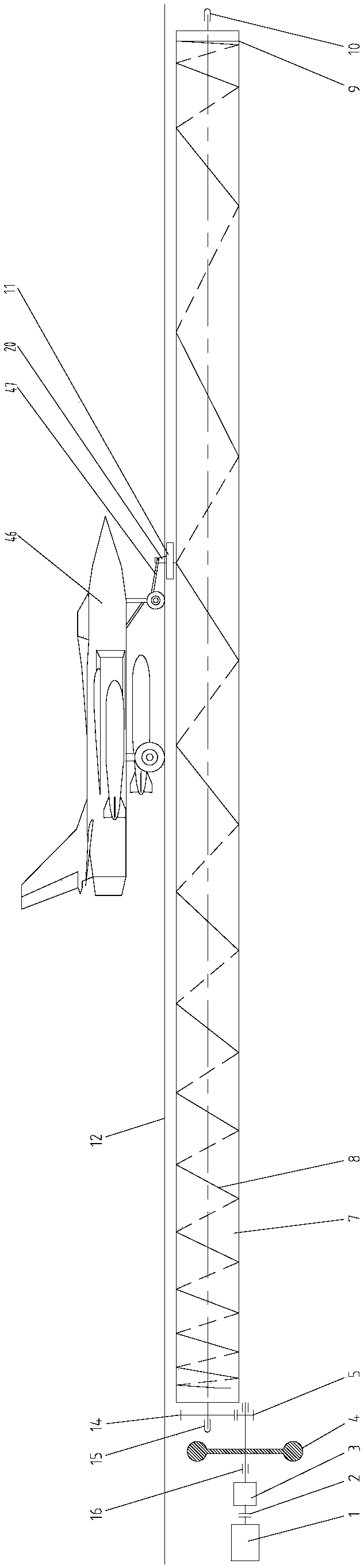
[0088] The carrier-based aircraft catapult described in this embodiment is a mechanical ejection device with flywheel energy storage and variable pitch screw drive. figure 1 . The ejection device mainly includes a prime mover 1, a hydraulic torque converter 2, a transmission 3, a flywheel 4, a variable pitch screw 7, a retractable slider 6, a traction trolley 11 and a track 17, except that the traction hook 20 on the top of the traction trolley 11 extends out of the aircraft carrier The aircraft carrier disassembles the deck 12, and the rest are all installed in the catapult ground groove 48 below the aircraft carrier's removable deck 12 on the take-off runway; the prime mover 1 drives the flywheel 4 and the variable pitch screw 7 to accelerate rotation through the transmission 3; The screw rod 7 stores the mechanical kinetic energy sent by the prime mover 1; the variable pitch screw rod 7 is installed under the slit 50 of the detachable deck 12, and the two ends of the variable
Embodiment 2
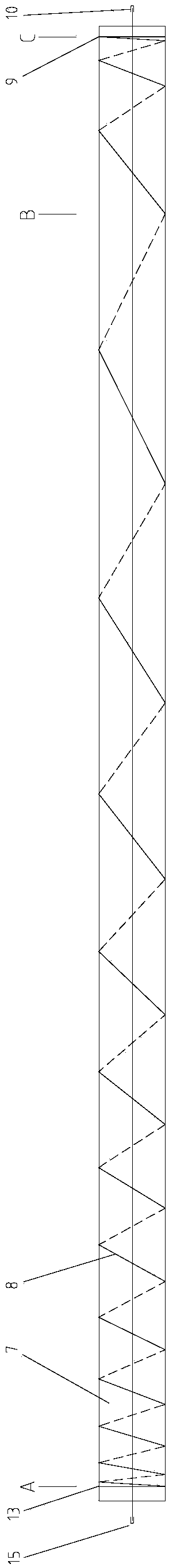
[0097] This embodiment is a simplified version of the present invention, see figure 2. The ejection device mainly includes a motor, a variable pitch screw, a retractable slider, a traction trolley and a track, and the main difference with Embodiment 1 is that it omits the hydraulic torque converter 2, the speed changer 3, and the flywheel 4, and adopts the motor 21 as Prime movers, especially for ships with sufficient electrical power.
[0098] The variable pitch screw 7 in this embodiment is a thick-walled hollow tube with a length of about 70m, a diameter of 3.2m, a wall thickness of 0.06m, and a weight of 320t. The outer side of the hollow tube is processed with a spiral groove 8, and the length of the acceleration section is about 59m. The length of the deceleration section is about 10 meters, and the maximum helix angle β at the end of the acceleration section reaches 45°. The moment of inertia of the variable pitch screw rod 7 itself is huge enough to act as a flywheel.
Embodiment 3
[0103] This embodiment is a multi-slider hydraulic automatic equalization force mechanism, see Figure 6 ~ Figure 8 . The device mainly includes a group of acceleration buffer hydraulic cylinders 38 , a group of deceleration buffer hydraulic cylinders 36 and an air bag type accumulator 45 . Each group of buffer hydraulic cylinders includes a group of independent one-way piston cylinders 51, pistons 40 and push rods 39, and the hydraulic lines 41 of all one-way piston cylinders 51 are connected and provided by the air bag accumulator High pressure hydraulic oil 42. A group of hydraulic cylinders connected by hydraulics can automatically adjust the position of the telescopic slider 6 relative to the traction car in the forward direction to adapt to the change of the helix angle β of the spiral groove 8, and at the same time balance the telescopic cylinders of different telescopic sliders 6 35 of the acting force. Each group of one-way piston hydraulic cylinders can only bear the
PUM
 Abstract
Description
Claims
Application Information
 - R&D Engineer
- R&D Manager
- IP Professional
- Industry Leading Data Capabilities
- Powerful AI technology
- Patent DNA Extraction
Browse by: Latest US Patents, China's latest patents, Technical Efficacy Thesaurus, Application Domain, Technology Topic.
© 2024 PatSnap. All rights reserved.Legal|Privacy policy|Modern Slavery Act Transparency Statement|Sitemap