Emergency speed changing box

A technology of gearbox and gearbox body, which is applied to transmission parts, non-mechanical transmission locks, gear transmissions, etc. Effect

Pending Publication Date: 2019-01-22
深圳市罗漫斯智能家居有限公司
View PDF0 Cites 2 Cited by
  • Summary
  • Abstract
  • Description
  • Claims
  • Application Information

AI Technical Summary

Problems solved by technology

[0005] The technical problem to be solved by the present invention is to provide an emergency gearbox for the above-m

Method used


Image

  • Emergency speed changing box
  • Emergency speed changing box
  • Emergency speed changing box

Examples


Embodiment Construction

[0024] Now in conjunction with the accompanying drawings, the preferred embodiments of the present invention will be described in detail.

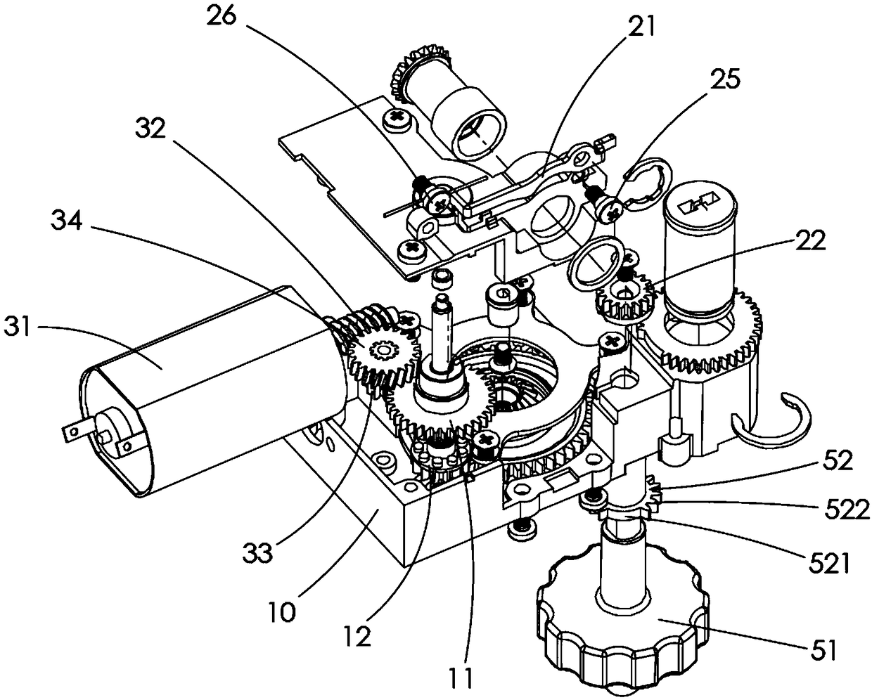
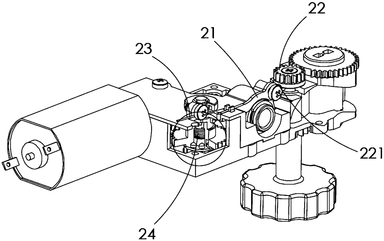
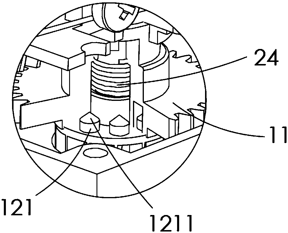
[0025] Such as Figure 1 to Figure 6 As shown, the present invention provides a preferred embodiment of an emergency gearbox.

[0026] Specifically, an emergency gearbox, the emergency gearbox is installed on a lock, and is used to drive the lock to unlock. The emergency gearbox includes a gearbox body 10, a power output gear set, an automatic power input gear set driven by a motor 31 in the gearbox body 10, and a clutch between the power output gear set and the automatic power input gear set. The emergency gearbox also includes an emergency assembly. In the power failure state, the emergency assembly drives the clutch assembly to complete the clutch operation. At this time, the automatic power input gear set does not drive the power output gear set to output power, but changes The power output gear set is driven by the emergency component


PUM


Abstract

The invention relates to the field of door lock accessories, in particular to an emergency speed changing box. The emergency speed changing box comprises a speed changing box body, a power output gearassembly, an automatic power input gear assembly, a clutch assembly, an emergency knob, a clutch matching piece connected with the emergency knob and a driving gear, when the clutch matching piece rotates along with the emergency knob, the clutch assembly can be driven to be in a separation or combination state; the driving gear comprises an engaged region and an avoidance region, the engaged region is engaged with the power output gear assembly, and the avoidance region is separated from the power output gear assembly; when the driving gear rotates to be engaged with the power output gear assembly along with the emergency knob, the clutch matching piece drives the clutch assembly to be in a separated state; and when the driving gear rotates to be separated from the power output gear assembly along with the emergency knob, the clutch matching piece drives the clutch assembly to be in a combined state. When in a power failure state, the emergency knob is twisted, then, separation and combination and unlocking operation can be finished synchronously, and the emergency speed changing box is quite simple and convenient to operate.

Description


Claims


Application Information

Patent Timeline
Owner 深圳市罗漫斯智能家居有限公司
Why Eureka
Try Eureka