Wing connector

A technology of connectors and wings, which is applied to aircraft parts, fuselage, transportation and packaging, etc., can solve problems such as broken wings, machine damage, and wing shaking, and achieve the effect of saving production costs

Inactive Publication Date: 2019-01-25
江苏云端智能科技有限公司
View PDF0 Cites 0 Cited by
  • Summary
  • Abstract
  • Description
  • Claims
  • Application Information

AI Technical Summary

Benefits of technology

This invention relates to an aircraft that has wings connected by connectors with movable parts for better control over its movement during operation. By controlling this connection between different components or devices within it, there are benefits such as reducing damage caused when operating at higher speeds without affecting the safety of other nearby structures like pilots or airplanes.

Problems solved by technology

The technical problem addressed by this patented method for improving flight safety during aerial photographing involves ensuring that all wings stay steady while still being able to move freely without getting loose or breaking down easily.

Method used


Image

  • Wing connector

Examples


Embodiment Construction

[0010] In order to make the object, technical solution and advantages of the present invention clearer, the present invention will be further described in detail below through the accompanying drawings and embodiments. However, it should be understood that the specific embodiments described here are only used to explain the present invention, and are not intended to limit the scope of the present invention.

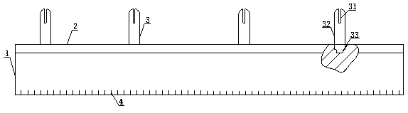
[0011] like figure 1 As shown, a kind of wing connector that the present invention adopts comprises support 1, guide rail 2, clip device 3, scale 4, groove 31, clamping plate 32 and plug 33, and one end of support 1 is fixedly connected guide rail 2, A scale 4 is engraved on the surface of the bracket 1, and at least two clip devices 3 are connected to the bracket 1 through guide rails 2. The clip device 3 is composed of a groove 31, a clip 32 and a plug 33. There is a rectangular groove 31 above the round head-shaped clamp 32, the end of the clamp 32 is fixedly connected t


PUM

PropertyMeasurementUnit
Lengthaaaaaaaaaa
Lengthaaaaaaaaaa

Abstract

The invention discloses a wing connector comprising brackets, guide rails, clip devices, a scale, groove, cardboard and plugs, one end of the bracket is fixedly connected with a guide rail, the surface of the bracket is engraved with a scale, at least two of the clip devices are connected to the bracket via a guide rail, the card device comprises a groove, a card board and a plug, a rectangular groove is formed above the round-headed card plate, the end of the card plate is fixed with the connecting plug, the length of the groove is 3 cm to 8 cm, the width of the plug is the same as the widthof the guide rail, the position of the wing connector can be adjusted according to the actual need, the phenomenon that the wing is broken due to environmental reasons can be effectively prevented, the flight equipment can not fall from a high altitude, the machine on the flight equipment can not be damaged, and the production cost can be greatly saved.

Description


Claims


Application Information

Patent Timeline
Owner 江苏云端智能科技有限公司
Why Eureka
Try Eureka