Magnetic integration device for planar transformer and inductor

A planar transformer and magnetic integration technology, which is applied in the directions of transformer/inductor magnetic core, transformer/inductor parts, transformer/inductor coil/winding/connection, etc., can solve the problems of complex magnetic circuit and large volume, and achieve Good safety, good heat dissipation effect, and cost reduction effect

Active Publication Date: 2019-03-15
广州迈斯宝新能源科技有限公司
View PDF1 Cites 0 Cited by
  • Summary
  • Abstract
  • Description
  • Claims
  • Application Information

AI Technical Summary

Benefits of technology

This patented technology helps create smaller electronic devices with better coolability while maintaining their reliability. Additionally, there's also improved energy utilization compared to traditional designs for these products. Overall, this innovative design improves both functionality and durability over existing technological solutions.

Problems solved by technology

Technological Problem: Current On Board Charger (OBC) systems require multiple components such as power transistors for regulation or voltage conversion. These devices can be expensive due to their complexity and size requirements. To solve this problem, designers have focused on integrating them into one component called Planar Transformer/Inductor(PT). However, current designs still involve complicated structures with high volumes.

Method used


Image

  • Magnetic integration device for planar transformer and inductor
  • Magnetic integration device for planar transformer and inductor
  • Magnetic integration device for planar transformer and inductor

Examples


Embodiment Construction

[0023] The specific implementation manners of the present invention will be further described in detail below in conjunction with the accompanying drawings and embodiments. The following examples are used to illustrate the present invention, but are not intended to limit the scope of the present invention.

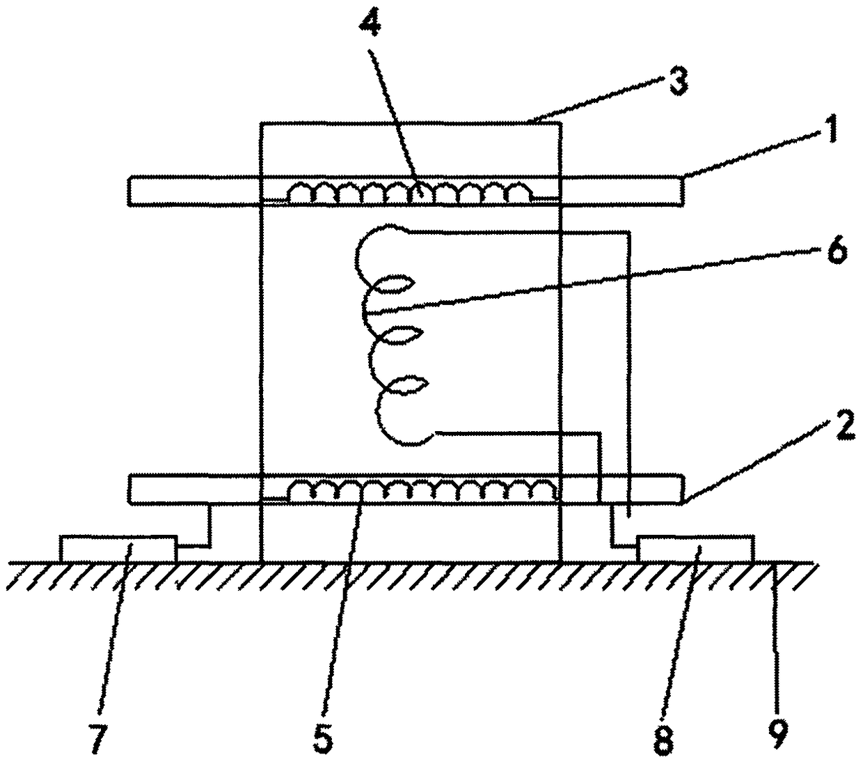
[0024] Such as Figures 1 to 2 As shown, a preferred embodiment of the magnetic integration device of the example planar transformer and inductance of the present invention includes: a magnetic core, and the magnetic core is provided with two opposite first circuit boards 1 and a second circuit board 2. A first planar winding 4 is arranged on the first circuit board 1, a second planar winding 5 is arranged on the second circuit board 1, and a separate winding 6 or a third planar winding 5 is arranged on the magnetic core. Windings, the first planar winding, the second planar winding and the discrete winding constitute the transformer and the excitation inductance respectivel


PUM


Abstract

The invention relates to a magnetic integration device for a planar transformer and an inductor. The magnetic integration device comprises a magnetic core, wherein two opposite circuit board windingsare arranged on the magnetic core; the two circuit board windings and a discrete winding are coupled together through the magnetic core; and the two circuit boards belong to a primary loop and a secondary loop respectively and are insulated from each other and are only magnetically coupled; and the circuit boards are electrically connected to a switch tube group.

Description


Claims


Application Information

Patent Timeline
Owner 广州迈斯宝新能源科技有限公司
Why Eureka
Try Eureka