Power conversion device

A technology of power conversion device and DC voltage conversion, which is applied in the direction of electronic commutation motor control, electrical components, motor control, etc., can solve the problems such as the inability to realize the driving characteristics and the difficulty in estimating the magnetic pole position.

Active Publication Date: 2019-04-02
HITACHI IND EQUIP SYST CO LTD
View PDF6 Cites 0 Cited by
  • Summary
  • Abstract
  • Description
  • Claims
  • Application Information

AI Technical Summary

Problems solved by technology

[0005] Most of the practical sensorless control utilizes the induced voltage generated by the rotation of the synchronous motor. Therefore, the estimation of the magnetic pole position is very difficult when the induced voltage is small or does not generate the induced voltage near zero speed or in the low-speed region and in the stopped state. Difficult, there is a problem that the desired drive characteristics cannot be achieved

Method used


Image

  • Power conversion device
  • Power conversion device
  • Power conversion device

Examples


Embodiment 1

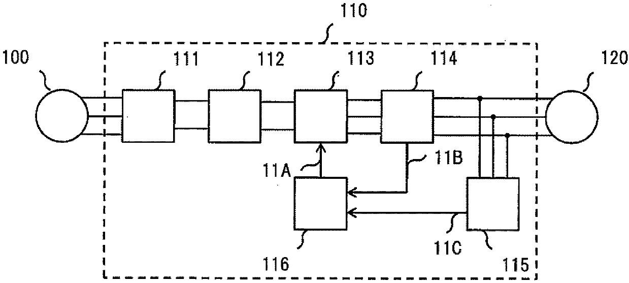
[0037] use figure 1 The control system for driving a synchronous motor according to the present embodiment and the overall configuration of a power conversion device equipped with the control system will be described.

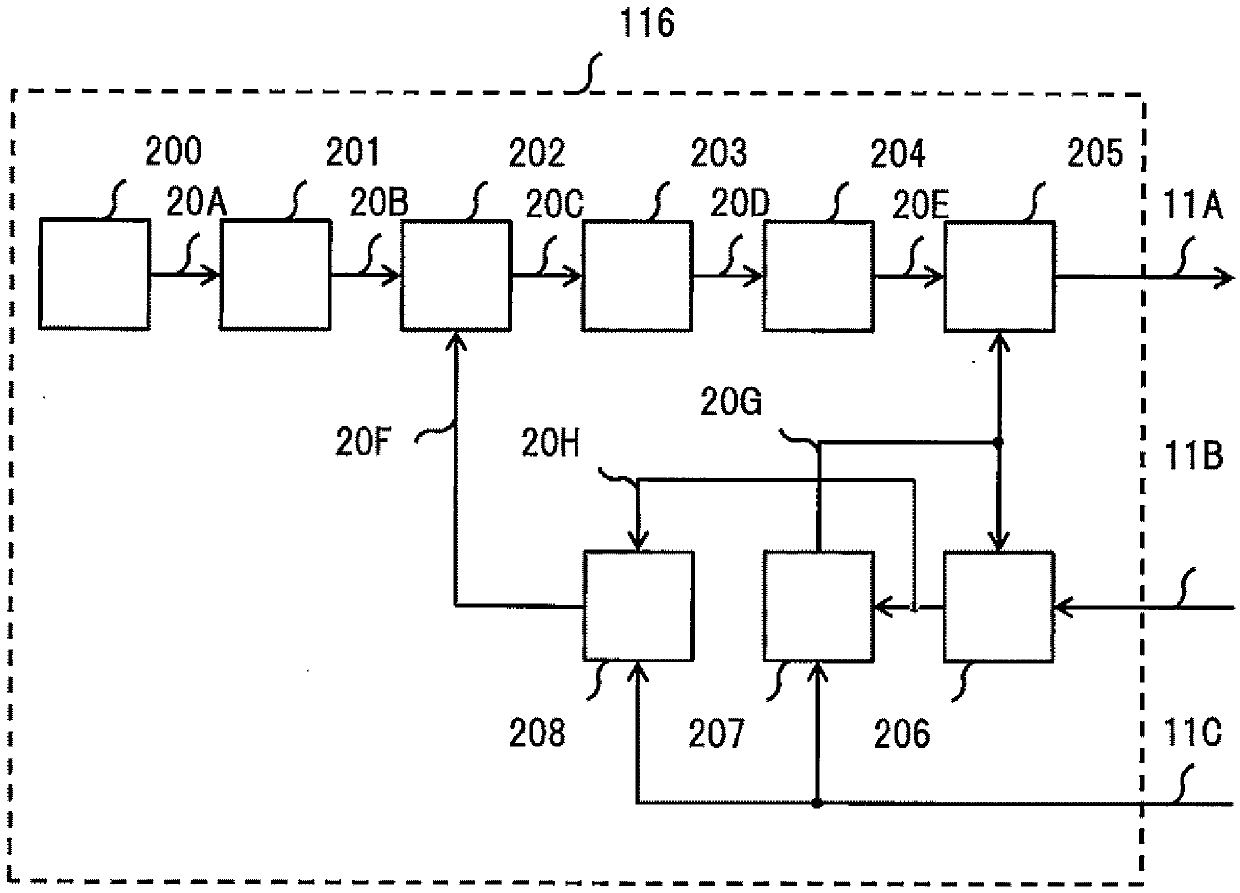
[0038] A power conversion device 110 for driving a three-phase AC synchronous motor 120 includes a rectification circuit 111 , a smoothing circuit 112 , a switch circuit 113 , a current detection circuit 114 , a voltage detection circuit 115 , and a motor control unit 116 .

[0039] The three-phase AC voltage output from the three-phase AC power supply 100 is rectified by the rectification circuit 111 and smoothed by the smoothing circuit 112 to generate a DC voltage. A single-phase AC power supply may be used instead of the three-phase AC power supply 100 to rectify and smooth the single-phase AC voltage to generate a DC voltage. The rectification circuit 111 and the smoothing circuit 112 can also be removed, and the DC voltage can be obtained directly from t...

Embodiment 2

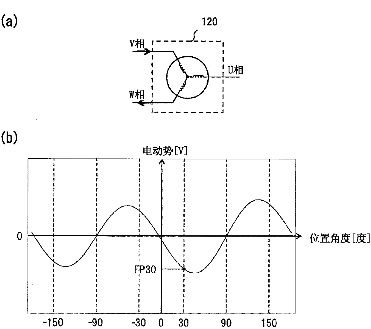
[0097] Embodiment 1 describes a driving method when the torque required for the rotor of the synchronous motor increases and the current also increases due to load generation. However, depending on the characteristics of the synchronous motor, the magnetic saturation electromotive force is sometimes affected not only by the magnitude of the current but also by the direction of the current. In such a synchronous motor, when the load fluctuates and the direction of the current flowing in the energized phase is reversed, for example, when the power running state is changed to the regenerative state, if only the magnitude of the current is considered as in the first embodiment If the magnetic pole position is detected, the magnetic pole position may not be detected accurately. Therefore, this embodiment is characterized in that the magnetic pole position is detected in consideration of the current direction as well as the magnitude of the current, and the three-phase AC synchronou...


PUM


Abstract

The purpose of the present invention is to provide a power conversion device capable of obtaining driving characteristics desired around zero speed and in a low speed region regardless of how much magnetic saturation electromotive voltage is affected by current. The power conversion device converts an AC voltage or a DC voltage to an arbitrary AC voltage to control a three-phase AC synchronous electric motor and is characterized by being provided with a control unit for controlling the three-phase AC synchronous electric motor in six energizing modes by selecting two phases to be energized from among the three phase windings of the three-phase AC synchronous electric motor, wherein said control unit estimates the magnetic pole position of the three-phase AC synchronous electric motor on the basis of the detected voltage of a non-energized phase of the three phase windings and the detected current of an energized phase of the three phase windings and controls the three-phase AC synchronous electric motor using the estimated magnetic pole position.

Description

technical field [0001] The present invention relates to power conversion devices. Background technique [0002] Power conversion devices that drive electric motors are used in technical fields such as industrial machinery, home appliances, and automobiles. Power conversion devices in these fields widely use synchronous motors provided with permanent magnets. [0003] In order to drive this synchronous motor, it is necessary to know the magnetic pole position information of the permanent magnets in the synchronous motor, so a position sensor for detecting the magnetic pole position is necessary. [0004] However, a technology called sensorless control has begun to spread. This technology does not use a position sensor to obtain information on the magnetic pole position, but instead estimates the magnetic pole position to drive a synchronous motor. This sensorless control includes, for example, a method of detecting the induced voltage (speed electromotive force) generated b...

Claims


Application Information

Patent Timeline
IPC IPC(8): H02P27/06
CPCH02P6/185H02P6/10H02P23/03H02P2203/03
Inventor 大矢将登
Owner HITACHI IND EQUIP SYST CO LTD
Why Eureka
Try Eureka