Driving device, fluid utilization device, and air conditioner
A drive device and synchronous motor technology, applied in the direction of control of electromechanical transmission, motor control, motor generator control, etc., can solve the problem of cost increase, and achieve the effect of inhibiting the rotation from becoming unstable
- Summary
- Abstract
- Description
- Claims
- Application Information
AI Technical Summary
Problems solved by technology
Method used
Image

Examples
Embodiment approach 1
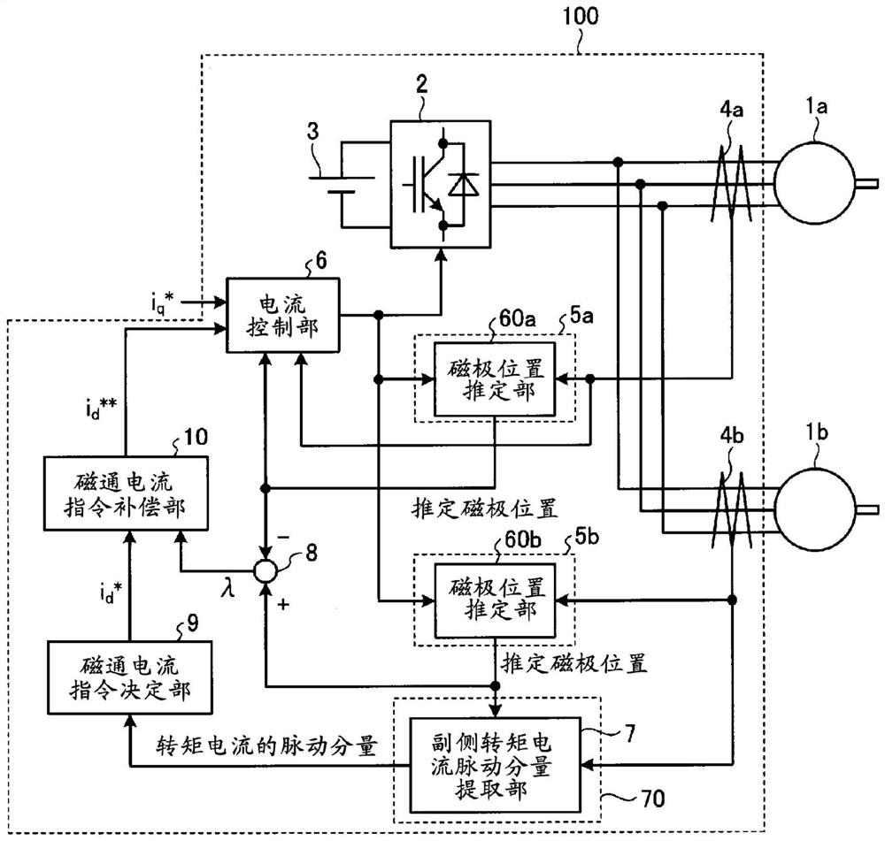
[0065] figure 1 It is a diagram showing a configuration example of the drive device according to Embodiment 1 of the present invention. Synchronous motors are broadly classified into permanent magnet field type synchronous motors in which permanent magnets are installed on the rotor, wound field type synchronous motors in which field windings are wound on the rotor, and saliency of the rotor. A reluctance synchronous motor that obtains rotational torque. Two synchronous motors of the same type among these types of synchronous motors, for example, permanent magnetic field type synchronous motors, are connected in parallel to the drive device 100 of the first embodiment. In Embodiment 1, one of the two synchronous motors is referred to as a master-side synchronous motor 1a, and the other is referred to as a slave-side synchronous motor 1b. The master-side synchronous motor 1a is a first synchronous motor, and the slave-side synchronous motor 1b is a second synchronous motor.
[
Embodiment approach 2
[0193] In Embodiment 2, a configuration example in which a magnetic flux current is determined using a ripple component of the active power consumed by the secondary-side synchronous motor 1b will be described. In order to solve technical problems such as increased noise and vibration, and reduced motor efficiency, it is necessary to accurately detect the self-oscillation phenomenon of the secondary synchronous motor 1b caused by motor elastic resonance even under the condition of a large change in magnetic flux current. One method for this is the method using the ripple component of the torque current described in the first embodiment. However, when the load connected to the primary synchronous motor 1a and the secondary synchronous motor 1b, that is, the moment of inertia of the mechanical system is relatively large, the magnetic flux can be determined by using the pulsating component of the active power instead of the pulsating component of the torque current. current. As des
Embodiment approach 3
[0204] Figure 27 It is a diagram showing a configuration example of a drive device according to Embodiment 3 of the present invention. The driving device 100B of Embodiment 3 includes a pulsation component extraction unit 70B instead of figure 1 The pulsation component extractor 70 is shown. The pulsating component extracting unit 70B includes the secondary torque current pulsating component extracting unit 7 , the primary torque current pulsating component extracting unit 12 , and the subtractor 8 a. Other structures are the same or equivalent to those of Embodiment 1, and the same or equivalent structural parts are given the same reference numerals and repeated descriptions are omitted.
[0205] In Embodiment 3, it is determined based on the difference between the torque current ripple component that is the ripple component of the torque current of the secondary synchronous motor 1b and the torque current ripple component that is the ripple component of the torque current of
PUM
 Abstract
Description
Claims
Application Information
 - R&D Engineer
- R&D Manager
- IP Professional
- Industry Leading Data Capabilities
- Powerful AI technology
- Patent DNA Extraction
Browse by: Latest US Patents, China's latest patents, Technical Efficacy Thesaurus, Application Domain, Technology Topic.
© 2024 PatSnap. All rights reserved.Legal|Privacy policy|Modern Slavery Act Transparency Statement|Sitemap