Spark cutting machine dust collecting and removing device of casting workshop

A technology for foundry and dust removal device, applied in shearing devices, manufacturing tools, metal processing mechanical parts, etc., can solve the problems of complex structure, high cost, lack of cooling and filtering, etc., to avoid damage and avoid damage.

Active Publication Date: 2019-04-26
山东蓝清环境工程有限公司
View PDF11 Cites 1 Cited by
  • Summary
  • Abstract
  • Description
  • Claims
  • Application Information

AI Technical Summary

Problems solved by technology

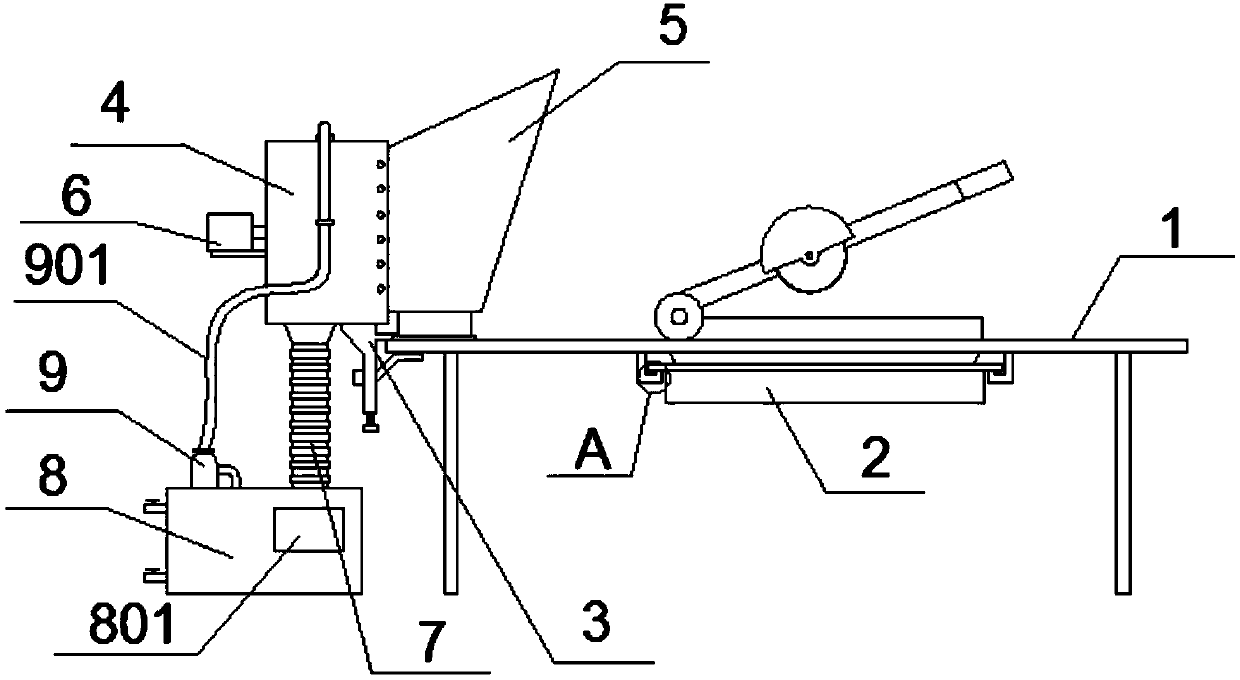
[0007] To sum up, the present invention provides a spark cutting machine collecting and dust removal device in a foundry, through structural and functional improvements, to solve the problems of complex structure and high cost of commonly used equipment, and lack of cooling and filtering functions

Method used


Image

  • Spark cutting machine dust collecting and removing device of casting workshop
  • Spark cutting machine dust collecting and removing device of casting workshop
  • Spark cutting machine dust collecting and removing device of casting workshop

Examples


Example Embodiment

[0035] The embodiments of the present invention will be described in further detail below in conjunction with the drawings and examples. The following examples are used to illustrate the present invention, but cannot be used to limit the scope of the present invention.

[0036] In the description of the present invention, unless otherwise specified, "plurality" means two or more; the terms "upper", "lower", "left", "right", "inner", "outer" , "Front", "Back", "Head", "Tail", etc. indicate the orientation or positional relationship based on the orientation or positional relationship shown in the drawings, and are only for the convenience of describing the present invention and simplifying the description, not It indicates or implies that the pointed device or element must have a specific orientation, be constructed and operated in a specific orientation, and therefore cannot be understood as a limitation of the present invention. In addition, the terms "first", "second", "third", et


PUM


Abstract

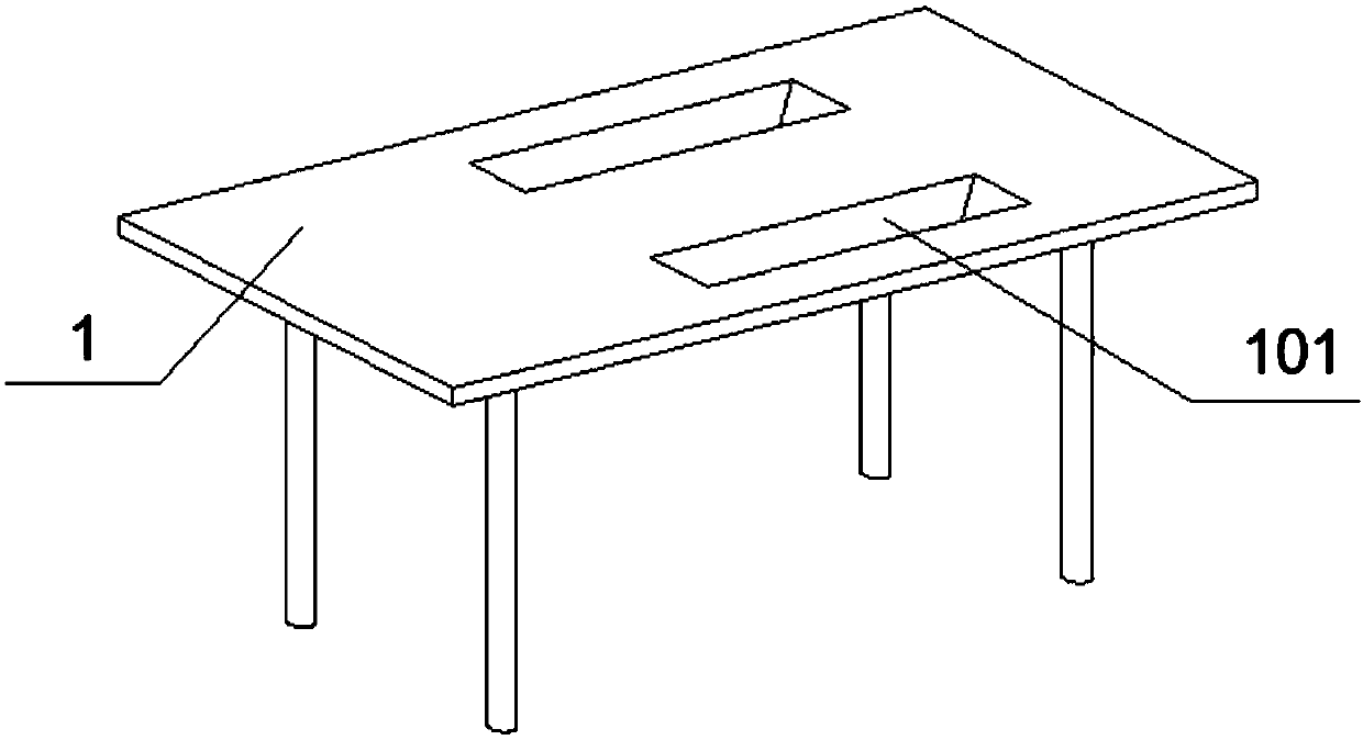
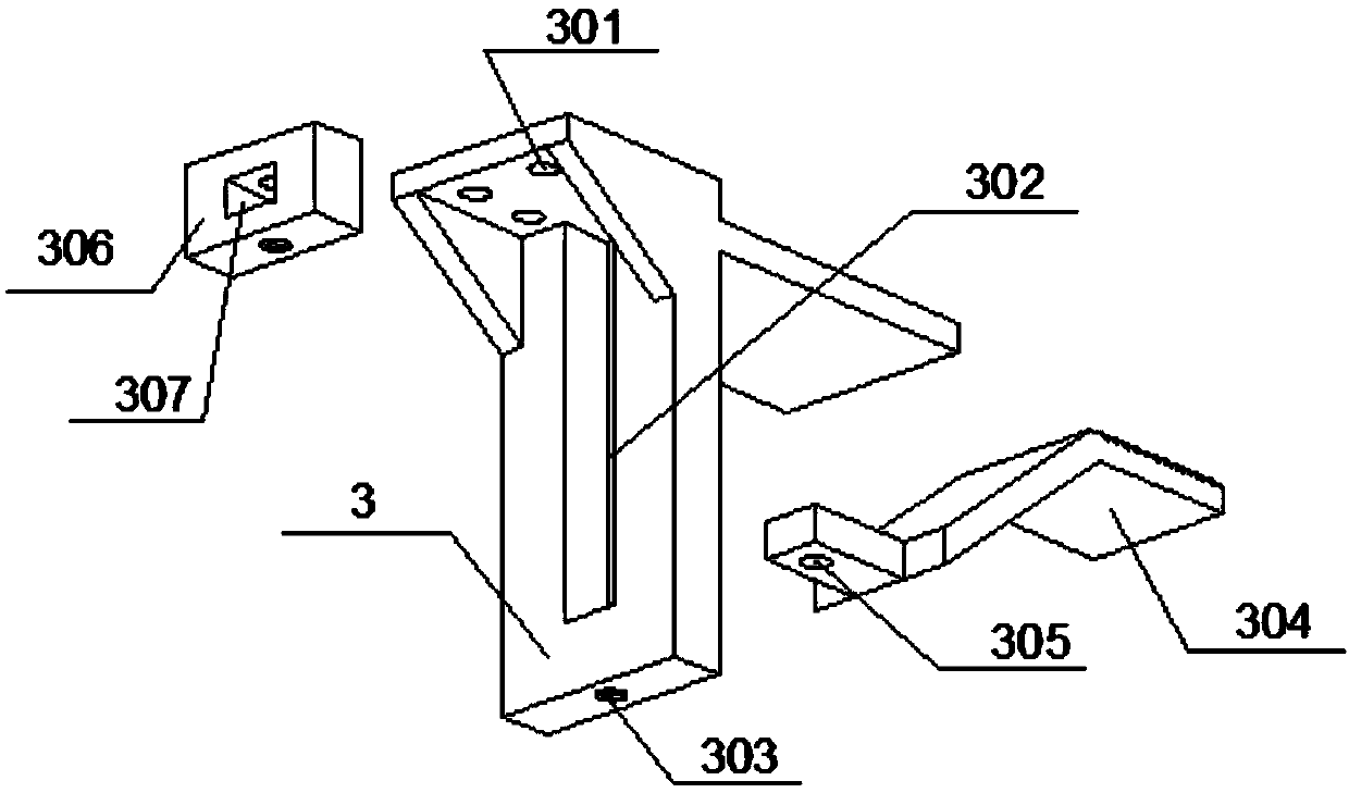
The invention provides a spark cutting machine dust collecting and removing device of a casting workshop. The device comprises a cutting table, dust holes, strip hooks, a movable tray, pulleys, a table side clamp, fixed holes, a movable hole, a locking screw hole, a suction fan, a folding connecting pipe, a filter water tank, a filter net box, a filter net, a water inlet joint, a water draining joint, a connecting pipe hole, a water suction hole, a circular pump and a water pipe. The movable hole is formed in the middle of the table side clamp, the bottom of the movable hole penetrates throughthe locking screw hole in the table side clamp, a connecting hole is formed in the bottom of a table bottom clamp, 12 sets of connecting holes A are formed in the two sides of the outer portion of acollection box, 12 sets of connecting holes B are formed in the two sides of one end of an auxiliary plate, the auxiliary plate penetrates through the connecting holes A and the connecting holes B through bolts to be fixedly arranged at one end of the collecting box, a movable tray and the pulleys are arranged, clearing of the cutting table is facilitated, cleaning efficiency is improved, and theinfluence of stacking of scrap ion on the cutting can be effectively avoided.

Description


Claims


Application Information

Patent Timeline
Owner 山东蓝清环境工程有限公司
Why Eureka
Try Eureka