Composite mandrel for fiber pipe weaving

A combination of mandrel and fiber tube technology, applied in the field of fiber tube manufacturing, can solve problems such as difficulty in taking out the mandrel

Pending Publication Date: 2019-07-02
HENAN UNIV OF SCI & TECH
View PDF11 Cites 0 Cited by
  • Summary
  • Abstract
  • Description
  • Claims
  • Application Information

AI Technical Summary

Problems solved by technology

[0004] The purpose of the present invention is to provide a combined mandrel for fiber tube braiding, which

Method used


Image

  • Composite mandrel for fiber pipe weaving
  • Composite mandrel for fiber pipe weaving
  • Composite mandrel for fiber pipe weaving

Examples


Embodiment Construction

[0026] The specific embodiments of the present invention will be further described below in conjunction with the accompanying drawings.

[0027] Embodiments of the combined mandrel for fiber tube braiding provided by the present invention:

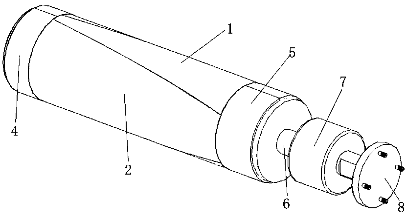
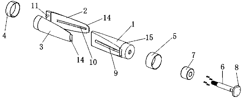
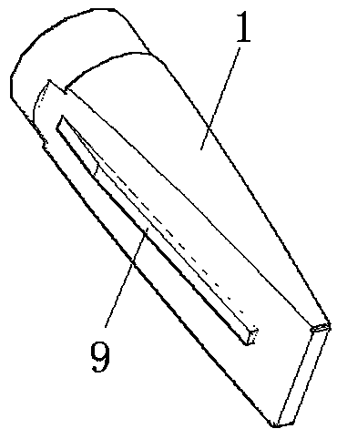
[0028] Such as figure 1 with figure 2 As shown, the combined mandrel for fiber tube braiding includes a first plug-in component 1 and a second plug-in component that are plug-fitted. The first plug-in component 1 extends along the front-to-back direction, and the second plug-in component has a The slot where the plug-in part 1 is inserted. After the first plug-in part 1 is plugged into the second plug-in part, together with the second plug-in part, the formed outer peripheral surface whose axis extends in the front and rear direction is formed. The shaped outer peripheral surface is used for supplying Filament winding and braiding; in this embodiment, the first plug-in component 1 is metal.

[0029] It is defined that the first plug-in co


PUM


Abstract

The invention relates to the technical field of fiber pipe manufacturing, in particular to a composite mandrel for fiber pipe weaving. The composite mandrel for fiber pipe weaving comprises a first inserting connection part and a second inserting connection part; the first inserting connection part extends in the front-back direction; the second inserting connection part comprises two or more forming sheet bodies extending in the front-back direction, the front ends of the forming sheet bodies are fixed relatively, the rear ends of the forming sheet bodies are suspended, and the suspended parts of the forming sheet bodies are arranged at intervals and form inserting grooves for allowing the first inserting connection part to be inserted from back to front; the first inserting connection part and the second inserting connection part are inserted in the front-back direction and jointly form a forming periphery surface of which the axis extends in the front-back direction, and the formingperiphery surface is used for fiber winding, weaving and forming; and the inserting matched surfaces of the first inserting connection part and the second inserting connection part are wedge surfaces. The composite mandrel for fiber pipe weaving can be used for solving the problem that in the prior art, a mandrel cannot be easily pulled out from a fiber pipe.

Description


Claims


Application Information

Patent Timeline
Owner HENAN UNIV OF SCI & TECH
Why Eureka
Try Eureka