Design method of flyback switching power supply transformer shield windings

A technology for shielding windings and switching power supplies, applied in transformer/inductor noise damping, adjusting electrical variables, instruments, etc., can solve the problems of power supply products that are difficult to meet relevant EMC standards, electronic load interference, lack of solutions, etc., and achieve ideal common Mode noise suppression effect, low production cost, obvious effect of common mode suppression effect

Active Publication Date: 2018-01-19
ZHEJIANG UNIV
View PDF2 Cites 7 Cited by
  • Summary
  • Abstract
  • Description
  • Claims
  • Application Information

AI Technical Summary

Benefits of technology

This patented technology improves on existing designs for prevention or reduction of unwanted electromagnetic interference (EMI). It allows for easy fabrication without adding unnecessary components that could cause problems such as overheating or other issues during operation. Additionally, it simplifies the structure of conventional EMC systems by eliminating certain parts altogether, making them lighter than traditional ones. Overall, this new design helps improve electronic equipment's performance at high frequencies.

Problems solved by technology

This technical problem addressed in this patents relates to improving the performance of switches while reducing electromagnetic emissions (EME). Specifically, existing methods have limitations such as requiring large filters or adding extra components like ground terminals. Therefore, an effective way to prevent unwanted signals from affecting circuitry becomes necessary.

Method used


Image

  • Design method of flyback switching power supply transformer shield windings
  • Design method of flyback switching power supply transformer shield windings
  • Design method of flyback switching power supply transformer shield windings

Examples


Embodiment Construction

[0037] In order to describe the present invention more specifically, the technical solutions of the present invention will be described in detail below in conjunction with the accompanying drawings and specific embodiments.

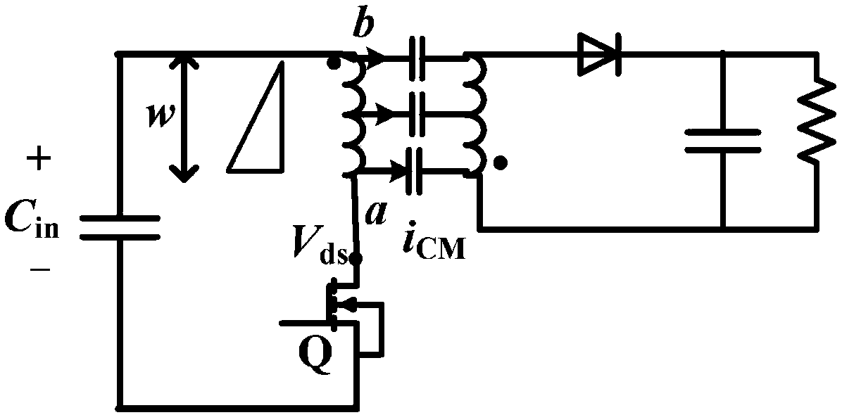
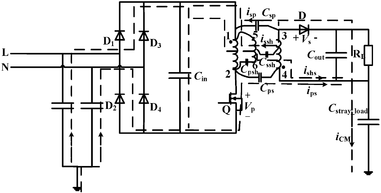
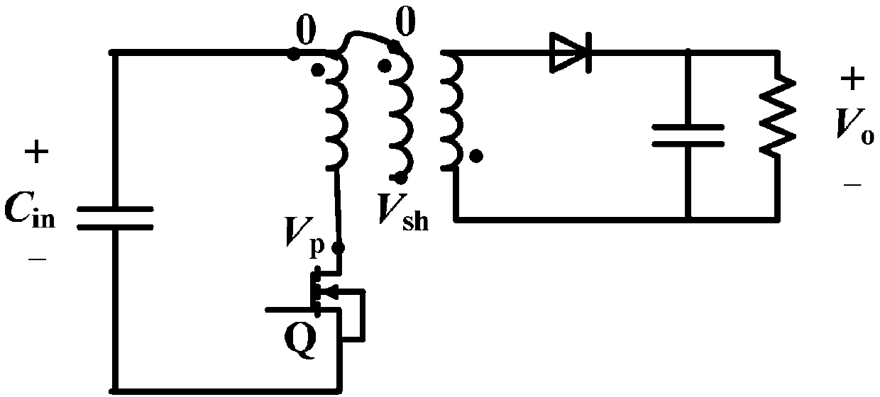
[0038] The transformer shielding winding design method of the flyback switching power supply of the present invention obtains the structure between the windings of the transformer (including the primary and secondary windings, the primary and secondary auxiliary windings and the shielding winding) under the condition of using different shielding winding turns through the simulation software Capacitance, and then use the common-mode current equivalent coefficient formula to draw the characteristic curve of the functional relationship between the common-mode current equivalent coefficient and the number of turns of the shielding winding, and finally determine the number of turns of the shielding winding when the common-mode current is the smallest, specifically


PUM


Abstract

The invention discloses a design method of flyback switching power supply transformer shield windings. The design method comprises the steps of (1) selecting a transformer, determining a connection type of the transformer shield windings, and measuring a structural dimension of the transformer, (2) setting turns of the shield windings as fixed values, and obtaining structural capacitance between the windings of the transformer under the different turns of the shield windings by utilizing simulation software, (3) calculating a common mode current equivalence coefficient in the transformer underthe different turns of the shield windings, and drawing a function relation characteristic curve of the common mode current equivalence coefficient and the turns of the shield windings, and (4) obtaining the turns of the shield windings when the common mode current equivalence coefficient is minimum according to the drawn characteristic curve, namely the optimal turns of the shield windings for inhibiting common mode current of the transformer. Compared with the existing common mode inhibition technique, the method has the advantages of simple device manufacturing, low realization cost, overall device weight and volume reduction, obvious inhibition effect and the like.

Description


Claims


Application Information

Patent Timeline
Owner ZHEJIANG UNIV
Why Eureka
Try Eureka