Method for extracting CO and H2 from raw gas

A raw gas and purified gas technology, applied in the chemical industry, can solve problems such as increased operating costs and equipment, ineffective use of heat, and high energy consumption for hydrogen recovery, achieving low equipment investment and operating costs, high reliability, and improved efficiency Effect

Pending Publication Date: 2019-07-12
WUHUAN ENG
View PDF1 Cites 2 Cited by
  • Summary
  • Abstract
  • Description
  • Claims
  • Application Information

AI Technical Summary

Problems solved by technology

But there are the following problems: (1) in order to improve the hydrogen recovery rate, the tail gas recovery device adopts a membrane separation system to carry out multiple hydrogen recovery. Although the hydrogen recovery rate has been improved on the surface, there is low purity of the hydrogen product and the hydrogen recovery capacity. The problem of high consumption; (2) the regen

Method used


Image

  • Method for extracting CO and H2 from raw gas
  • Method for extracting CO and H2 from raw gas

Examples


Example Embodiment

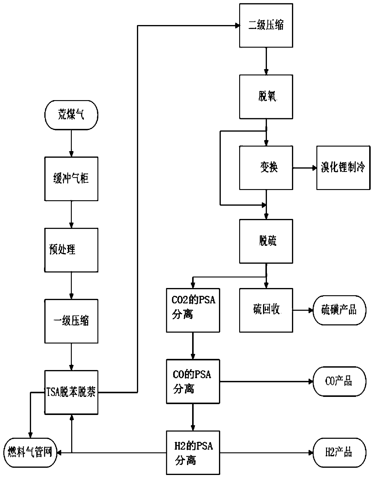
[0016] The present invention will be further explained below in conjunction with the drawings:

[0017] See figure 1 , A process for extracting CO and H2 from raw gas, including the following steps:

[0018] (1) The raw gas is pre-treated after passing through the buffer gas tank: the tar in the raw gas is removed by the electric flutter, and the concentration of the tar in the raw gas after treatment is lower than 1mg / Nm3, and the raw gas after pretreatment is obtained;

[0019] (2) One-stage compression: the raw gas after the pretreatment is compressed in one stage to obtain the compressed raw gas, and the outlet pressure of the first-stage compression is 0.3MPa(G);

[0020] (3) TSA removal of benzene and naphthalene: After pressurization, the raw gas is cooled by heat exchange with low-temperature water and the temperature is reduced to 15-20 ℃, and then TSA is debenzene and naphthalene removed to obtain raw gas after benzene and naphthalene removal. The TSA operating pressure is 0.


PUM


Abstract

The invention discloses a method for extracting CO and H2 from raw gas. According to the technical scheme, through decoking pretreatment of raw gas, first-stage compression, TSA debenzolization and naphthalene removal, two-stage compression, deoxidation, a transformation reation and desulfuration, purified gas is obtained; the purified gas undergoes three stages of PSA separation to successively separate CO2, CO and H2 to finally obtain desorbed gas; part of or the whole desorbed gas is used as a recovered medium to be sent to the TSA debenzolization and naphthalene removal process for recycling by an adsorption tower; and the recycled desorbed gas containing benzene and naphthalene is used as fuel gas to be sent to the outside. The method of the invention has simple process, is energy-saving and consumption-reducing, has low production cost and operation cost, is used to effectively extract CO and H2 in raw gas to realize full utilization of raw gas constituent and reduce environmental pollution.

Description


Claims


Application Information

Patent Timeline
Owner WUHUAN ENG
Why Eureka
Try Eureka