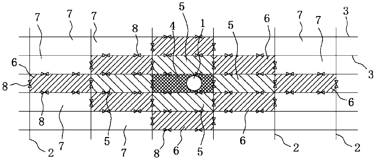
Arrangement method of ballast tank drain holes

An arrangement method and technology of flowing water holes, which are applied in the directions of ship construction, ships, and ship safety, etc., can solve problems such as delay in delivery, no specific specifications for the layout and use of water holes, and rules affecting the efficiency of shipyards, so as to avoid blocking. , to avoid the impact of structural strength and reinforcement work, to ensure the effect of structural strength

Inactive Publication Date: 2019-07-26
GUANGZHOU SHIPYARD INTERNATIONAL LTD
View PDF7 Cites 0 Cited by
  • Summary
  • Abstract
  • Description
  • Claims
  • Application Information

AI Technical Summary

Benefits of technology

This patented technology helps prevent damage from foreign objects entering ships without affecting their performance. It involves partitioning different sections within the vessel for better control over how fluids enter/exit them based upon factors like pressure difference between two points along its length. Additionally, this division allows for more efficient use of space inside the boat compared to traditional methods where only one section has an intake point. Overall, these technical improvements improve the functionality and reliability of boats used for transportation purposes while minimizing any modifications made after construction.

Problems solved by technology

This technical problem addressed during this patented phase describes how important factors like weight transfer or pressure relief should also be taken into account when setting up ballasts within ships' internal decking systems. Current designs have limitations such as requiring too many small openings per unit length, causing delays due to excessive stress concentration caused by high sea levels, leading to reduced lifespan and potential damage if there were any leaks around these openings.

Method used


Image

  • Arrangement method of ballast tank drain holes

Examples


Embodiment Construction

[0033] In order to make the technical problems solved by the present invention, the technical solutions adopted and the technical effects achieved clearer, the technical solutions of the embodiments of the present invention will be further described in detail below in conjunction with the accompanying drawings. Obviously, the described embodiments are only the technical solutions of the present invention. Some, but not all, embodiments. Based on the embodiments of the present invention, all other embodiments obtained by those skilled in the art without creative efforts fall within the protection scope of the present invention.

[0034] In the description of the present invention, unless otherwise clearly specified and limited, the terms "connected", "connected" and "fixed" should be understood in a broad sense, for example, it can be a fixed connection, a detachable connection, or an integrated ; It can be a mechanical connection or an electrical connection; it can be a direct co


PUM


Abstract

The invention discloses an arrangement method of ballast tank drain holes. The arrangement method of the ballast tank drain holes comprises the following steps that S100, a ballast tank of a ship is divided into a plurality of areas while a ballast suction port serves as a center; S200, an outflow cross-sectional area summation of outflow drain holes of all the areas and an inflow cross-sectionalarea summation of all inflow drain holes are determined correspondingly; and S300, the number and positions of openings in all the areas are determined according to the outflow cross-sectional area summation and the inflow cross-sectional area summation. According to the arrangement method of the ballast tank drain holes, it can be ensured that outflow and inflow ballast water can keep up with aninflow and outflow speed of the ballast suction ports through the drain holes formed in all the areas of the ballast tank of the ship, the problem of ballast pump empty suction or ballast pump overload caused by blocking of structural pieces of the ship and an insufficient opening area of the drain holes is solved, effective injection and extraction of the ballast water of the ballast tank are ensured, the injection speed and the extraction speed of the ballast water are ensured, and extraction efficiency and injection efficiency of the ballast water are improved.

Description


Claims


Application Information

Patent Timeline
Owner GUANGZHOU SHIPYARD INTERNATIONAL LTD
Why Eureka
Try Eureka