Intelligent power grid control cabinet

A technology of smart grid and control cabinet, applied in the field of control cabinet, can solve problems such as short circuit of internal components, achieve good waterproof effect, ensure safety, and better heat dissipation effect

Active Publication Date: 2019-07-30
安徽省申运木业有限公司
View PDF9 Cites 2 Cited by
  • Summary
  • Abstract
  • Description
  • Claims
  • Application Information

AI Technical Summary

Problems solved by technology

However, the control cabinets installed on some roadsides for controlling street lamps are vulnerable to short-circuiting of internal components due to erosion by floods when floods occur. In

Method used


Image

  • Intelligent power grid control cabinet
  • Intelligent power grid control cabinet
  • Intelligent power grid control cabinet

Examples


Example Embodiment

[0020] In order to make it easy to understand the technical means, creative features, goals and effects achieved by the present invention, the present invention will be further explained below in conjunction with specific embodiments.

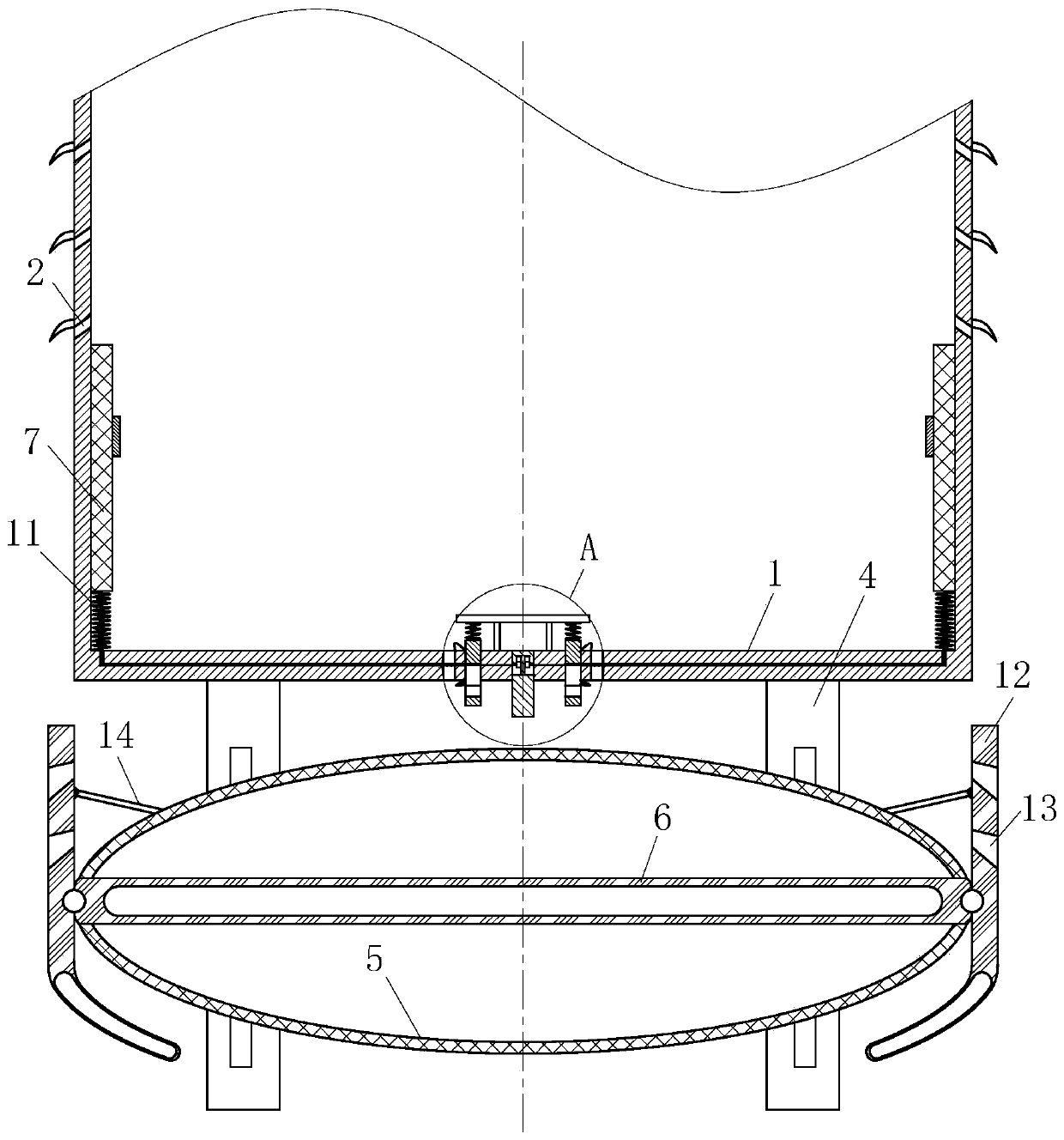
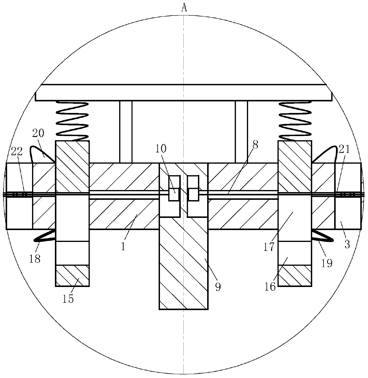
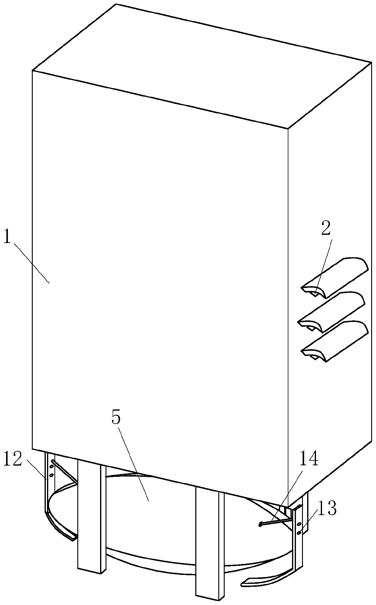
[0021] Such as Figure 1-3 As shown, a smart grid control cabinet according to the present invention includes a cabinet body 1 with main holes 2 on both sides of the cabinet body 1 and secondary holes 3 on the bottom wall thickness of the cabinet body 1. Legs 4 are fixedly connected to the bottom of the cabinet 1, a floating ball 5 is placed at the bottom of the cabinet 1, a hollow plate 6 is provided in the middle of the floating ball 5, and a sealing plate 7 is provided on the inner wall of the cabinet 1. A draw rope 8 is connected to the bottom of the sealing plate 7, a first push rod 9 is arranged at the center of the bottom of the cabinet body 1, a stop 10 is arranged at one end of the draw rope 8 and the stop 10 is arranged inside the first pus


PUM


Abstract

The invention belongs to the technical field of control cabinets, and particularly relates to an intelligent power grid control cabinet. The intelligent power grid control cabinet comprises a cabinetbody, wherein main holes are formed on the two sides of the cabinet body; auxiliary holes are formed on wall thickness of the bottom of the cabinet body; the bottom of the cabinet body is fixedly connected with landing legs; a floating ball is placed at the bottom of the cabinet body; a hollow plate is arranged in the middle of the floating ball; sealing plates are arranged on an inner wall of thecabinet body; the bottoms of the sealing plates are connected with pulling ropes; and a first push rod is arranged in the center of the bottom of the cabinet body. The intelligent power grid controlcabinet is provided with the auxiliary holes at the bottom of the cabinet body, the floating ball, and the main holes on the two sides of the cabinet body, so that a heat-dissipation effect of the cabinet body is good. When flood happens, the floating ball rises to push stop blocks of the first push rod to be moved out of the first push rod, the end parts of the pulling ropes can freely move, restoring forces of compression springs can push the sealing plates to seal the main holes, and finally the main holes and the auxiliary holes are sealed, so that a flood control effect is achieved, and the safety of components in the cabinet body is ensured.

Description


Claims


Application Information

Patent Timeline
Owner 安徽省申运木业有限公司
Why Eureka
Try Eureka