Grinding equipment for direct current (DC) plug plating layer

A plug and coating technology, applied in the field of DC plug coating grinding equipment, can solve the problems of inaccurate grinding position positioning, defective products, poor soldering, etc., and achieve the effect of avoiding pollution and high degree of automation

Pending Publication Date: 2019-08-02
深圳市优机智能技术有限公司
View PDF0 Cites 0 Cited by
  • Summary
  • Abstract
  • Description
  • Claims
  • Application Information

AI Technical Summary

Benefits of technology

The technical effect of this new technology is that it allows for better control over how much electricity flows through an electrical device compared to previous methods like manually welded connections or rubber seals used previously. This means less harm from exposure during maintenance work on these devices while still being able to maintain their efficiency.

Problems solved by technology

This technical problem addressed by this patented technology relates to improving methods used during electronic circuit assembly operations such as bond welds or flip-chip connections between semiconductor devices without damaging their electrical properties due to residue left from previous processing steps like cleanup after each step.

Method used


Image

  • Grinding equipment for direct current (DC) plug plating layer
  • Grinding equipment for direct current (DC) plug plating layer
  • Grinding equipment for direct current (DC) plug plating layer

Examples


Embodiment Construction

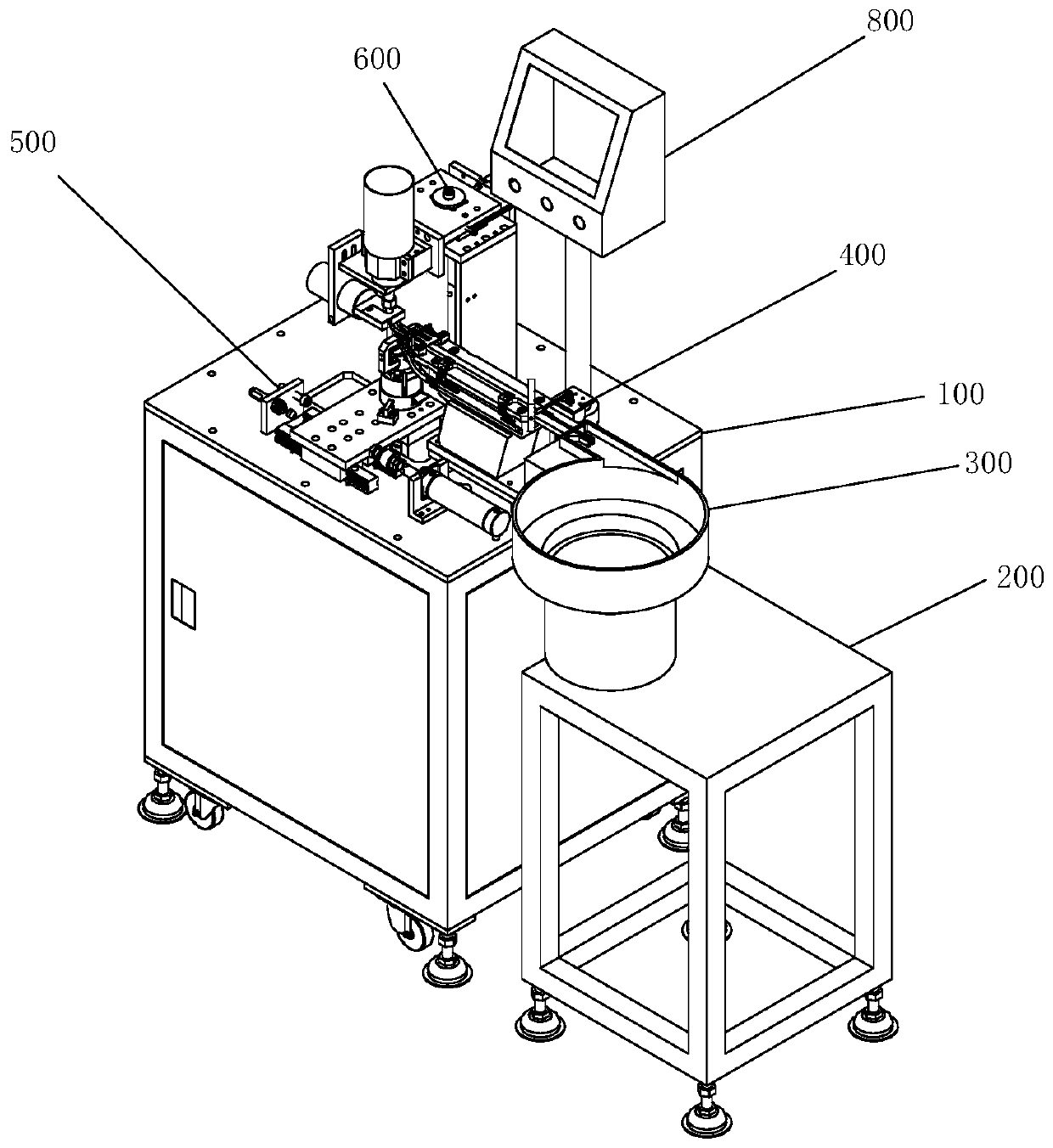
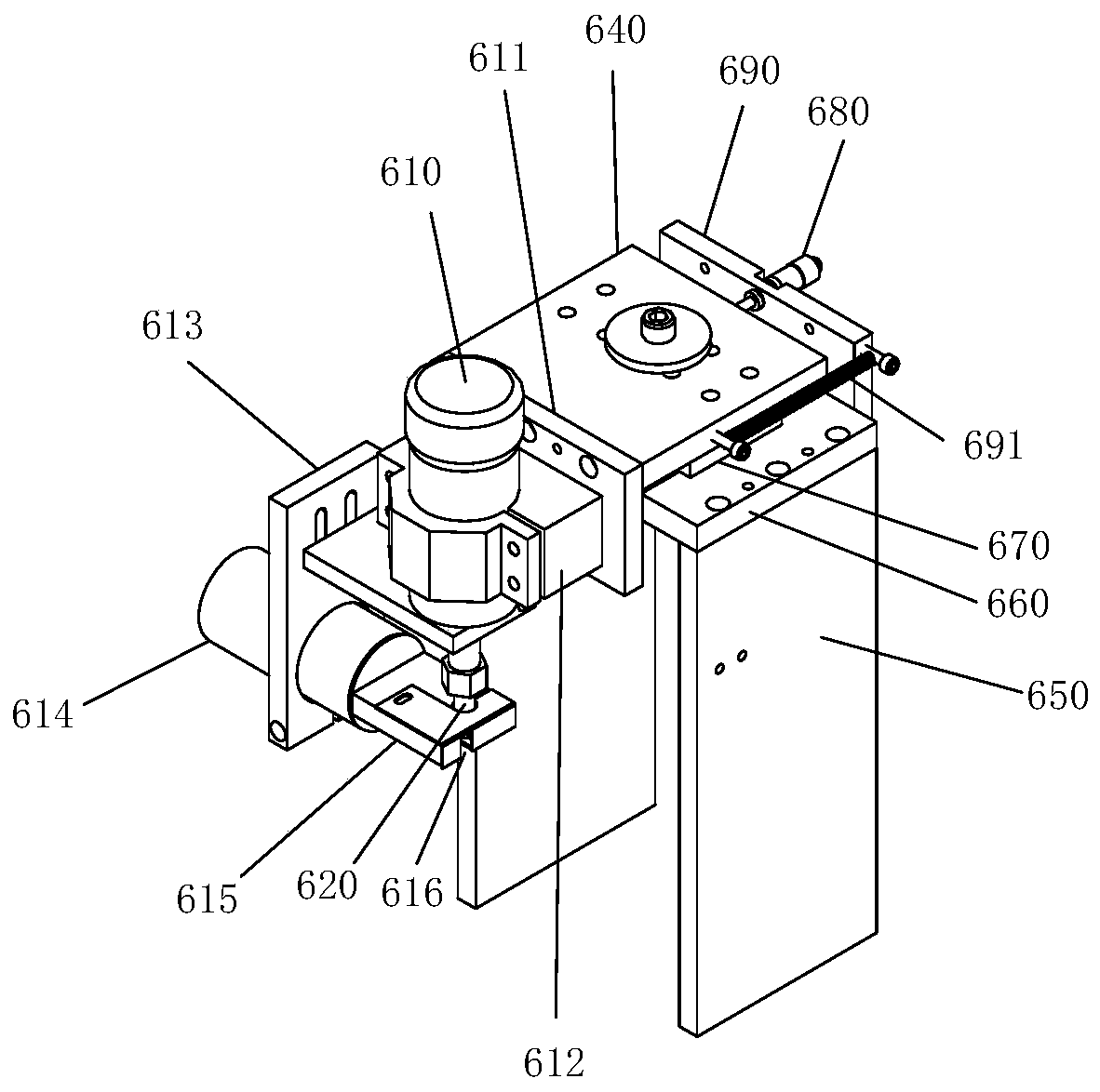
[0018] A kind of DC plug coating grinding equipment proposed by the present invention, such as figure 1 and figure 2 Shown, comprise: main frame 100 and vibrating plate frame 200 that are arranged side by side; Vibrating plate frame 200 is provided with feeding vibrating plate 300, and main frame 100 is provided with feeding mechanism 400, and the feeding end of feeding mechanism 400 and The feeding vibrating plate 300 is connected, and a material clamping translation mechanism 500 is provided outside the discharge end of the feeding mechanism 400, and a grinding mechanism 600 is provided above the material clamping translation mechanism 500; the grinding mechanism 600 includes: figure 2 Shown spindle motor 610, arbor 620, grinding tungsten steel blade (not shown), sliding support plate 640, two support vertical plates 650, linear guide rail fixing plate 660, linear guide rail 670, adjusting differential head 680, Separate the fixed plate 690 and the tension spring 691; two su


PUM


Abstract

The invention discloses grinding equipment for a direct current (DC) plug plating layer. A loading vibrating disk is arranged on a vibrating disk rack. A feeding mechanism is arranged on a main rack.The feeding end of the feeding mechanism is connected with the loading vibrating disk. A clamping translation mechanism is arranged on the outer side of the discharging end of the feeding mechanism. Agrinding mechanism is arranged above the clamping translation mechanism. A main shaft motor is in transmission connection with a tool-installing rod. A grinding tungsten steel blade is arranged on the tool-installing rod. A separate fixing plate is arranged on the side, away from the main shaft motor, of a sliding supporting plate. A dust collecting fixing plate is arranged on a motor fixing plate. A dust collecting hood is arranged at the position, corresponding to the position of the grinding tungsten steel blade, in the dust collecting fixing plate. A dust collecting hood closing cover isconnected to the dust collecting hood. The grinding tungsten steel blade is covered by the dust collecting hood closing cover, and a notch is formed in the dust collecting hood closing cover. The dustcollecting cover is connected with an industrial dust collector. By means of the technical scheme of the grinding equipment for the DC plug plating layer, full automation of grinding is achieved; residues can be cleaned in time in the grinding process; and follow-up plating of products is prevented from being influenced.

Description


Claims


Application Information

Patent Timeline
Owner 深圳市优机智能技术有限公司
Why Eureka
Try Eureka