Automatic shifting device

An automatic and rack-mounted technology, applied in the direction of transportation and packaging, conveyor objects, etc., can solve the problems of increasing equipment costs and labor costs, and achieve the effects of low cost, simple structure, and simple requirements

Pending Publication Date: 2019-08-09
SUZHOU HUQIANG ELECTRIC EQUIP
View PDF0 Cites 0 Cited by
  • Summary
  • Abstract
  • Description
  • Claims
  • Application Information

AI Technical Summary

Benefits of technology

This technology allows an automated shift mechanism used on conveyors to automatically move different parts between two locations without having any extra equipment or energy needed by other systems. It uses lift cylinders to transfer works from one location to another while still being able to hold them securely during transportation.

Problems solved by technology

The technical problem addressed by this patented technology is how to automatically shift works between different areas without increasing their complexity and expenses associated with manual operations for workers who want them to move around within the production process.

Method used


Image

  • Automatic shifting device
  • Automatic shifting device
  • Automatic shifting device

Examples


Embodiment Construction

[0018] The preferred embodiments of the present invention will be described in detail below in conjunction with the accompanying drawings, so that the advantages and features of the present invention can be more easily understood by those skilled in the art, so as to define the protection scope of the present invention more clearly.

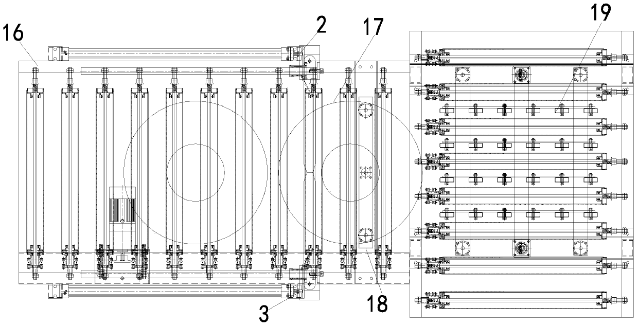
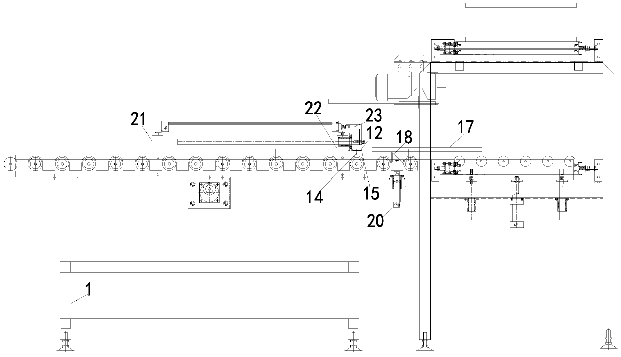
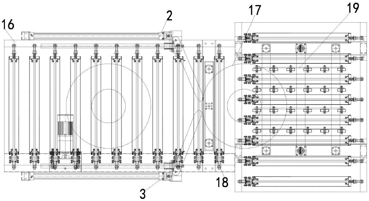
[0019] attached Figure 1-5 The automatic shifting device of the present invention includes a frame 1; the frame 1 is provided with a conveying line 16; the conveying line 16 is horizontally arranged on the same plane by conveying rollers (not shown); the The conveying roller is driven by a motor (not shown) to rotate on its own; one side of the frame 1 is provided with a first bracket 21 and a second bracket 22; the first bracket 21 and the second bracket 22 are provided with a first paddle Device 3; the first paddle device 3 includes a first electric cylinder 10, a first slide bar 11, a first paddle 12, a first return spring 13, a first rotating s


PUM


Abstract

The invention discloses an automatic shifting device. The automatic shifting device comprises a rack; a conveyor line is arranged on the rack; one side of the rack is provided with a first shift piecedevice; the first shift piece device comprises a first electric cylinder, a first sliding rod, a first shift piece, a first reset spring, a first rotating shaft and a first L-shaped frame; an outputshaft of the first electric cylinder and a first sliding rod shaft are connected to a first connecting block; the first shift piece is fixed on the rack through the first rotating shaft and can rotatefreely around the first rotating shaft; the first L-shaped frame is fixed on the first sliding rod shaft and can move horizontally with the first sliding rod; the first L-shaped frame is in point contact with the end face of the first shift piece; one end of the first reset spring is fixed on a second bracket and the other end of the first reset spring is fixed on the first shift piece; when thefirst shift piece rotates around the first rotating shaft, the first reset spring is pulled up to be in a state of tension; and a jacking plate is arranged in the middle of a conveying roller at the tail end of the transmission direction of the conveyor line, and a jacking cylinder is arranged at the bottom of the jacking plate.

Description


Claims


Application Information

Patent Timeline
Owner SUZHOU HUQIANG ELECTRIC EQUIP
Why Eureka
Try Eureka