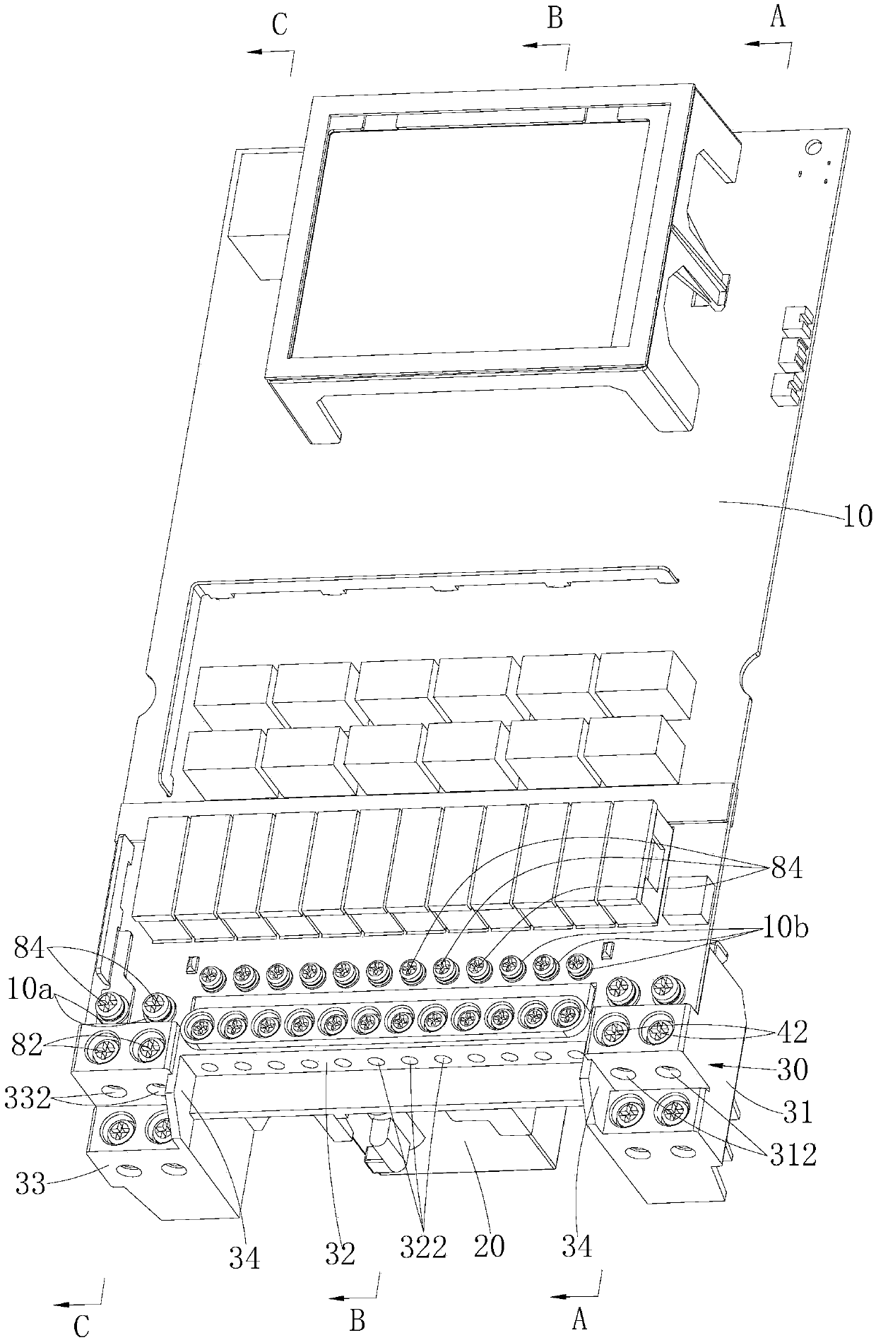
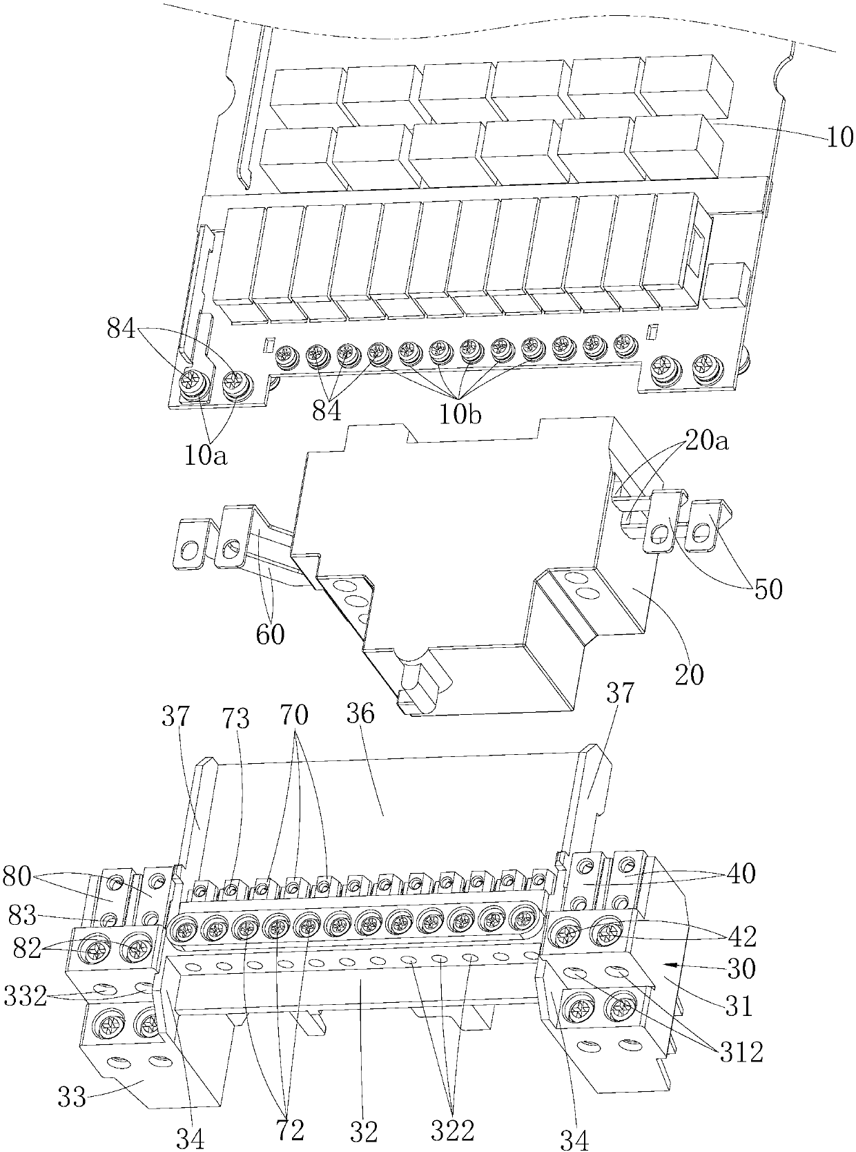
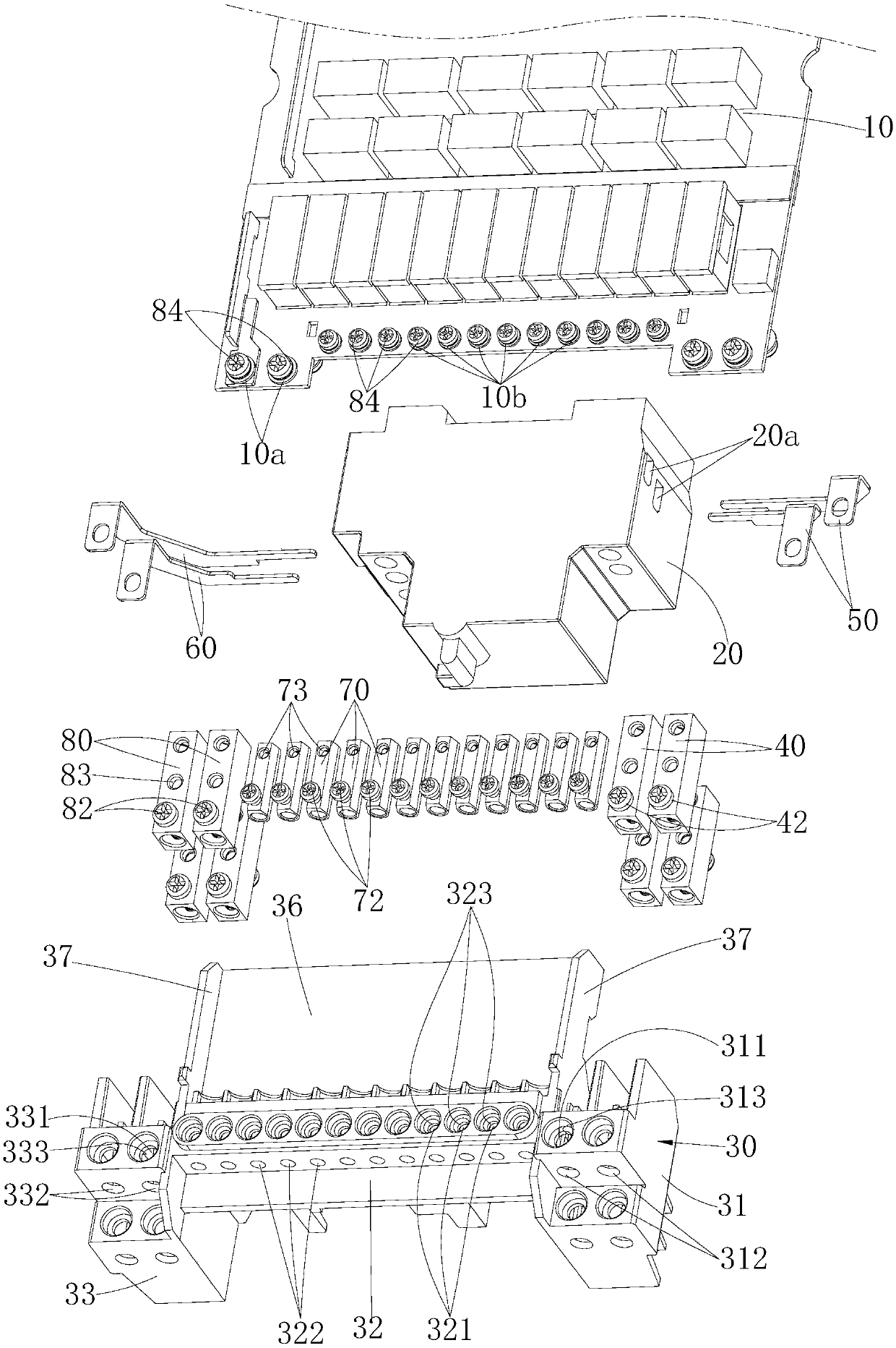
Assembly structure of circuit board and air switch, and charging pile

An air switch and assembly structure technology, which is applied to the circuit layout, circuit device, battery circuit device, etc. The effect of small space and convenient assembly or disassembly operation

Pending Publication Date: 2019-09-10
深圳智链物联科技有限公司
View PDF0 Cites 0 Cited by
  • Summary
  • Abstract
  • Description
  • Claims
  • Application Information

AI Technical Summary

Benefits of technology

This technology allows for efficient transmission of electrical energy between two different types of wires without adding extra parts like connectors. It achieves this by inserting an electric line at both ends of each type of cable separately before connecting them together. By controllably adjusting the voltage on either side of the signal lines based upon their location within the system's housing, it can achieve precise control over how much power they generate. Overall, these improvements make the design more effective than previous designs while also being easier to assemble/disassemble due to its compact size and easy-to-use components.

Problems solved by technology

Techn problem: Current circuits for controlling power supply have limitations such as requiring multiple components or complex connections between them due to their limited functionality. These issues can make it difficult to install these systems on smaller spaces without taking extra effort from designers who want more flexibility within control over how much electrical energy they consume during certain times of low-power operation.

Method used


Image

  • Assembly structure of circuit board and air switch, and charging pile
  • Assembly structure of circuit board and air switch, and charging pile
  • Assembly structure of circuit board and air switch, and charging pile

Examples


Embodiment Construction

[0035] In order to make the technical problems, technical solutions and beneficial effects to be solved by the present invention clearer, the present invention will be further described in detail below in conjunction with the accompanying drawings and embodiments. It should be understood that the specific embodiments described here are only used to explain the present invention, not to limit the present invention.

[0036] It should be noted that when an element is referred to as being “fixed” or “disposed on” another element, it may be directly on the other element or be indirectly on the other element. When an element is referred to as being "connected to" another element, it can be directly connected to the other element or indirectly connected to the other element.

[0037] It is to be understood that the terms "length", "width", "top", "bottom", "front", "rear", "left", "right", "vertical", "horizontal", "top" , "bottom", "inner", "outer" and other indicated orientations or


PUM


Abstract

The invention belongs to the technical field of air switch assembly structures, and more specifically, relates to an assembly structure of a circuit board and an air switch, and a charging pile. The end of an input wire is inserted into a first conductive tube, and the end of an output wire is inserted into a second conductive tube. An input power supply enters the input end of an air switch fromthe first conductive tube via a first conductive element and is output from the output end of the air switch, and the input power supply is input to the input position of a circuit board via a secondconductive element, controlled and processed by the circuit board and transported to the second conductive tube from the output position of the circuit board to realize power output. The circuit board, a mounting frame and the air switch are stacked in turn. The overall structure is compact and occupies less space. The circuit is simple, and the assembly or disassembly is convenient.

Description


Claims


Application Information

Patent Timeline
Owner 深圳智链物联科技有限公司
Why Eureka
Try Eureka