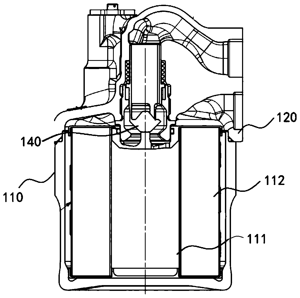
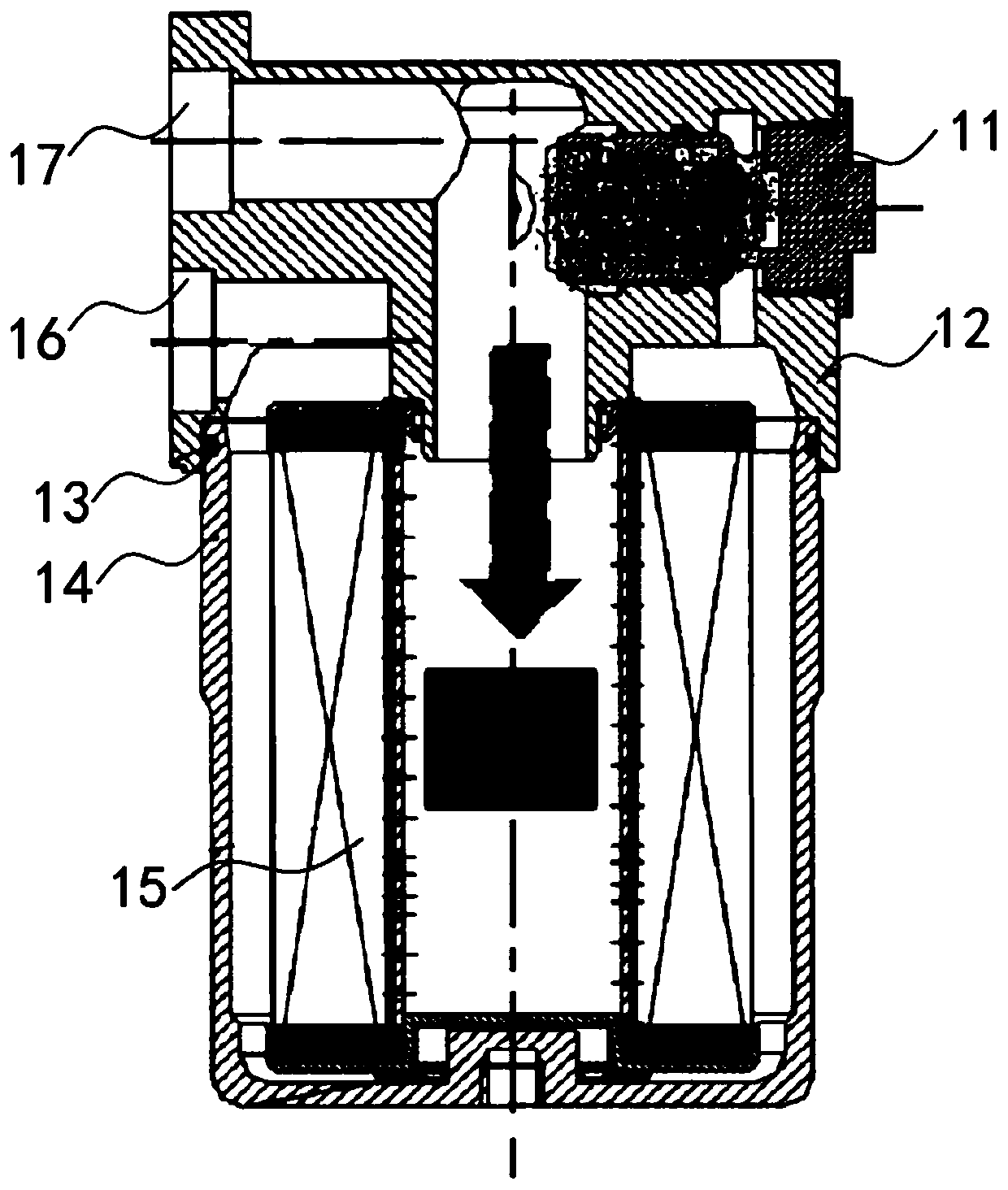
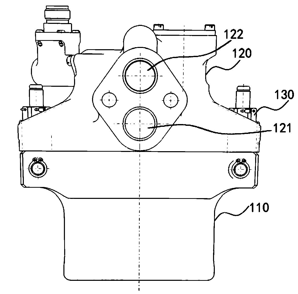
Lubricating oil filtering device
A filter device and lubricating oil technology, applied in the direction of filtration separation, transmission parts, gear lubrication/cooling, etc., can solve problems such as oil leakage, trimming of O-ring 13, and unchanged disassembly of the lubricating oil filter device, etc., to achieve The effect of quick installation and removal
- Summary
- Abstract
- Description
- Claims
- Application Information
AI Technical Summary
Benefits of technology
Problems solved by technology
Method used
Image

Examples
Embodiment Construction
[0052] Typical embodiments that embody the features and advantages of the present disclosure will be described in detail in the following description. It should be understood that the present disclosure can have various changes in different embodiments without departing from the scope of the present disclosure, and that the description and drawings therein are illustrative in nature and not intended to limit the present disclosure. public.
[0053] In the following description of various exemplary embodiments of the present disclosure, reference is made to the accompanying drawings, which form a part hereof, and in which are shown, by way of example, various exemplary structures, systems, which may implement aspects of the present disclosure and steps. It is to be understood that other specific arrangements of components, structures, exemplary devices, systems and steps may be utilized and structural and functional modifications may be made without departing from the scope of th
PUM
 Abstract
Description
Claims
Application Information
 - R&D Engineer
- R&D Manager
- IP Professional
- Industry Leading Data Capabilities
- Powerful AI technology
- Patent DNA Extraction
Browse by: Latest US Patents, China's latest patents, Technical Efficacy Thesaurus, Application Domain, Technology Topic.
© 2024 PatSnap. All rights reserved.Legal|Privacy policy|Modern Slavery Act Transparency Statement|Sitemap