Method and system for measuring extinction coefficient in correlation mode, and laser radar

A laser radar, extinction coefficient technology, applied in radio wave measurement systems, measurement devices, use of re-radiation and other directions, can solve problems such as non-compliance with actual conditions

Inactive Publication Date: 2019-10-15
DARSUNLASER HUANGSHAN TECH CO LTD
View PDF7 Cites 0 Cited by
  • Summary
  • Abstract
  • Description
  • Claims
  • Application Information

AI Technical Summary

Problems solved by technology

However, all the shortcomings of the existing technology are that most of them are currently measured by a laser radar. In processing laser radar signals, people often use Collis, Klett, Fernald and other algorithms to solve the laser radar equation, so as to invert the extinction coefficient of the atmosphere and visibility information
However, algorithms such as Collis, Klett, and Fernald are based on certain assumptions. However, many assumptions do not conform to the actual situation in reality.

Method used


Image

  • Method and system for measuring extinction coefficient in correlation mode, and laser radar
  • Method and system for measuring extinction coefficient in correlation mode, and laser radar
  • Method and system for measuring extinction coefficient in correlation mode, and laser radar

Examples


Example Embodiment

[0040] In order to better understand the technical solutions of the present invention, the embodiments provided by the present invention will be described in detail below with reference to the accompanying drawings.

[0041] The embodiment of the present invention provides a method for cross-beam measurement of extinction coefficient, which includes the following steps:

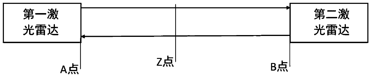
[0042] Step S1. A first lidar is set at point A, and a second lidar is set at point B. There is a point Z between the A point and the B point. In the embodiment, preferably, the first lidar and the second lidar are respectively arranged opposite to each other, and the first lidar and the second lidar may be placed relatively horizontally or not completely horizontally.

[0043] Step S2, the first lidar detects a first distance calibration signal from point A to point Z, and the value of the first distance calibration signal is RCS A (z), where RCS A (z)=C A ·Β(z)·exp(-2τ Az )(Formula 1));

[0044] The second lidar detec


PUM


Abstract

The invention provides a method and a system for measuring an extinction coefficient in a correlation mode, and a laser radar. The method is characterized by setting a first laser radar at a point A,and a second laser radar at a point B, wherein a point Z is located between the point A and the point B; and detecting a first distance calibration signal value from the point A to the point Z by a first laser radar, detecting a second distance calibration signal value from the point B to the point Z by a second laser radar, and calculating a ratio of the second distance calibration signal value and the first distance calibration signal value by the first laser radar. Through two opposite laser radars, an initial value of a laser radar equation and a laser radar ratio do not need to be assumedso that an atmospheric extinction coefficient and visibility can be accurately measured.

Description


Claims


Application Information

Patent Timeline
Owner DARSUNLASER HUANGSHAN TECH CO LTD
Why Eureka
Try Eureka