Process method for improving zeolite runner concentration ratio

A zeolite runner and process method technology, applied in separation methods, chemical instruments and methods, gas treatment and other directions, can solve the problems of increased fuel consumption, low calorific value self-circulation of desorbed gas concentration, etc., to reduce fuel consumption , the effect of improving the use effect

Inactive Publication Date: 2019-10-22
锦治环保科技(上海)有限公司
View PDF5 Cites 1 Cited by
  • Summary
  • Abstract
  • Description
  • Claims
  • Application Information

AI Technical Summary

Problems solved by technology

[0003] However, the concentration ratio of the zeolite runners of most zeolite runner manufacturers is usually no more than 25 times. We need to consider two aspects when determining the concentration ratio of the runner: one is the safety control of the concentration; the other is that the concentration can maintain the system Heat balance supply realizes self-circulation with little or no extra fuel, and the concentration of concentrated exhaust gas is controlled below 8g, within 25% of the lower explosion limit to ensure the safety of regenerative oxidat

Method used


Image

  • Process method for improving zeolite runner concentration ratio
  • Process method for improving zeolite runner concentration ratio
  • Process method for improving zeolite runner concentration ratio

Examples


Example Embodiment

[0027] The following will clearly and completely describe the technical solutions in the embodiments of the present invention with reference to the accompanying drawings in the embodiments of the present invention. Obviously, the described embodiments are only some, not all, embodiments of the present invention. Based on the embodiments of the present invention, all other embodiments obtained by persons of ordinary skill in the art without making creative efforts belong to the protection scope of the present invention.

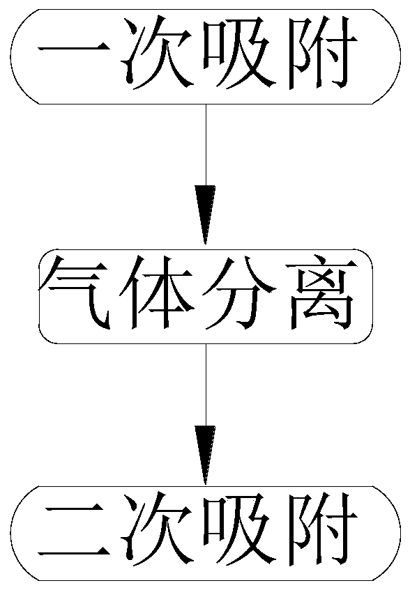
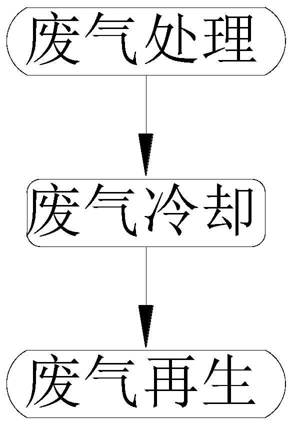
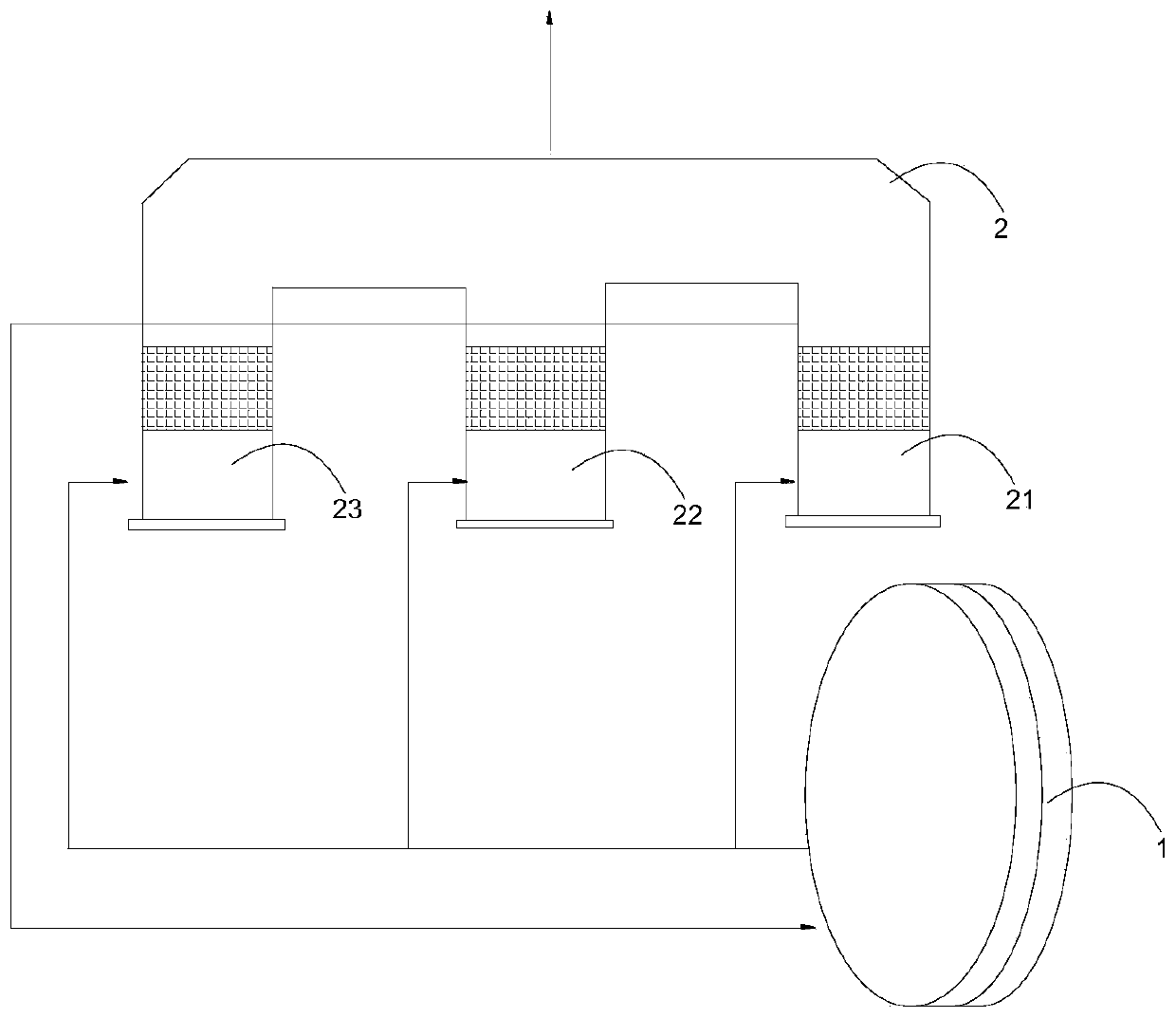
[0028] see Figure 1~4 , in the embodiment of the present invention, a process method based on increasing the concentration ratio of the zeolite runner, the process method at least includes a desorption, gas separation and secondary desorption in sequence; wherein,

[0029] Primary desorption: the same as desorbing the waste gas entering the zeolite runner 1, and simultaneously discharging the concentrated waste gas;

[0030] Gas separation: used to separate the


PUM


Abstract

The invention discloses a process method for improving a zeolite runner concentration ratio. The processing method comprises the following steps of orderly performing primary desorption, gas separation and secondary desorption. Numerous defects caused by the primary desorption of the traditional zeolite runner are abandoned, the secondary desorption of the waste gas is innovatively accomplished bycomprehensively utilizing a zeolite runner and a heat-accumulating type oxidizing furnace, thereby accomplishing the system heat self-circulation in the desorption process of the waste gas with the concentration less than 50 mg/ m<3>, and reducing the fuel consumption in the use process; and more importantly, the highest concentration ratio of the zeolite runner is changed to 49 times from 25 times, thereby greatly improving the use effect of the zeolite runner.

Description


Claims


Application Information

Patent Timeline
Owner 锦治环保科技(上海)有限公司
Why Eureka
Try Eureka