Test device with convenient installation and unloading for testing dynamic characteristics of seismic isolation building structure
A technology of dynamic characteristics and test devices, which is applied to building components, measuring devices, and the use of stable tension/pressure to test the strength of materials, etc., can solve problems such as waste of manpower and material resources, poor applicability, and difficulty in recycling support devices, and achieve convenience Effects of spring installation, simple structure, and improved accuracy and operability
- Summary
- Abstract
- Description
- Claims
- Application Information
AI Technical Summary
Benefits of technology
Problems solved by technology
Method used
Image

Examples
Embodiment 1
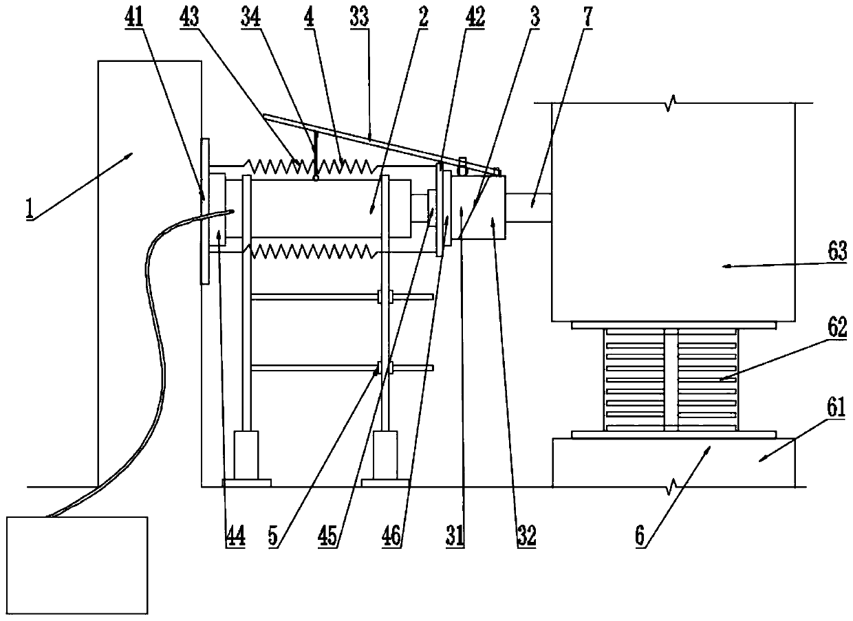
[0045] A test device for testing the dynamic characteristics of a seismically isolated building structure that is easy to install and unload, such as figure 1 , 7 As shown in and 8, including reaction wall 1, hydraulic jack 2, quick disassembly assembly 3, auxiliary disassembly assembly 4, hydraulic jack support mechanism 5 and shock-isolation support assembly 6;
[0046] The hydraulic jack 2 is installed horizontally on the hydraulic jack support mechanism 5, the base of the hydraulic jack 2 is provided with a reaction wall 1, and the top is provided with a vibration isolation support assembly 6 through the quick release assembly 3. The first unloading block 31 and the second unloading block 32 of the inclined plane, the auxiliary dismounting assembly 4 is installed between the base and the top of the hydraulic jack 2;
[0047] The hydraulic jack support mechanism 5 includes a first support plate 51, a second support plate 52, a horizontal screw 53 and a lifting leveling assemb
Embodiment 2
[0051] This embodiment is further improved on the basis of embodiment 1, as figure 1 , 2 , 3 and 6, the quick disassembly assembly 3 also includes a warping rod 33 and a clamping rod 34, one end of the warping rod 33 is provided with a warping rod slot 331, the other end is provided with a hook hole 332, and one end of the clamping rod 34 is hinged on the hydraulic jack 2, the other end is provided with a hook 341;
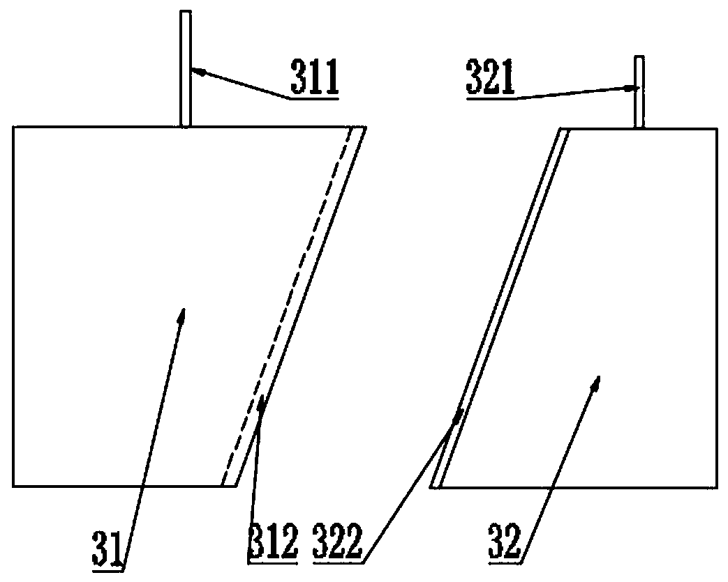
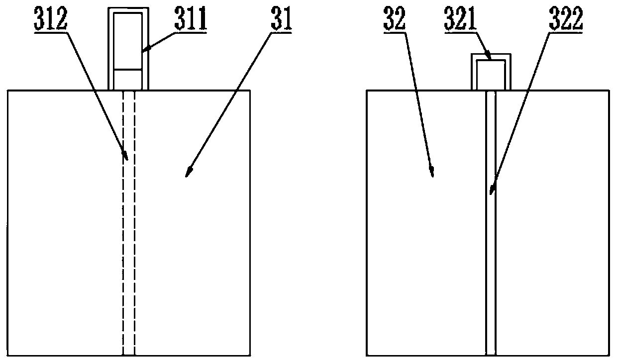
[0052] The first unloading block 31 and the second unloading block 32 are respectively provided with a door-shaped hook frame I311 and a door-shaped hook frame II321; the warping rod 33 passes through the door-shaped hook frame I311, and the warping rod slot 331 at one end is engaged with the door-shaped hook frame II 321, the hook hole 332 at the other end engages with the hook 341;
[0053] The slope of the first unloading block 31 is provided with a slot 312 , and the slot 312 is arranged along the inclined direction of the slope. The slope of the second unloadi
Embodiment 3
[0056] This embodiment is further improved on the basis of embodiment 1 or 2, as figure 1 , 4 As shown in and 5, the auxiliary disassembly assembly 4 includes a first connecting plate 41 installed on the base of the hydraulic jack 2, a second connecting plate 42 installed on the top of the hydraulic jack 2, and a spring connecting the first connecting plate 41 and the second connecting plate 42 43;
[0057] The first connecting plate 41 is provided with a first limiting groove 44 for engaging the base of the hydraulic jack, and the two sides of the second connecting plate 42 are respectively provided with a second limiting groove 45 for engaging the top of the hydraulic jack and the first unloading block 31 and The third limiting slot 46 , the first connecting plate 41 and the second connecting plate 42 are all provided with a connecting hook 47 connecting the spring 43 .
[0058] In specific use, by setting the first limiting groove 44, the second limiting groove 45 and the th
PUM
 Abstract
Description
Claims
Application Information
 - R&D Engineer
- R&D Manager
- IP Professional
- Industry Leading Data Capabilities
- Powerful AI technology
- Patent DNA Extraction
Browse by: Latest US Patents, China's latest patents, Technical Efficacy Thesaurus, Application Domain, Technology Topic.
© 2024 PatSnap. All rights reserved.Legal|Privacy policy|Modern Slavery Act Transparency Statement|Sitemap