Smart industry triggering emergency stop device

An industrial and intelligent technology, applied in electrical components, electrical switches, circuits, etc., can solve the problems of slowing down the speed of work and reducing the efficiency of work, and achieve the effects of precise control, use status and easy fault repair.

Inactive Publication Date: 2019-10-29
GANZHOU XIKE ENERGY SAVING AUTOMATION EQUIP CO LTD
View PDF0 Cites 2 Cited by
  • Summary
  • Abstract
  • Description
  • Claims
  • Application Information

AI Technical Summary

Problems solved by technology

[0004] The purpose of the present invention is to provide a smart industrial trigger emergency stop device to solve the problem mentioned above that the emergency stop device on the market is a single button struc

Method used


Image

  • Smart industry triggering emergency stop device
  • Smart industry triggering emergency stop device
  • Smart industry triggering emergency stop device

Examples


Embodiment Construction

[0017] The following will clearly and completely describe the technical solutions in the embodiments of the present invention with reference to the accompanying drawings in the embodiments of the present invention. Obviously, the described embodiments are only some, not all, embodiments of the present invention. Based on the embodiments of the present invention, all other embodiments obtained by persons of ordinary skill in the art without making creative efforts belong to the protection scope of the present invention.

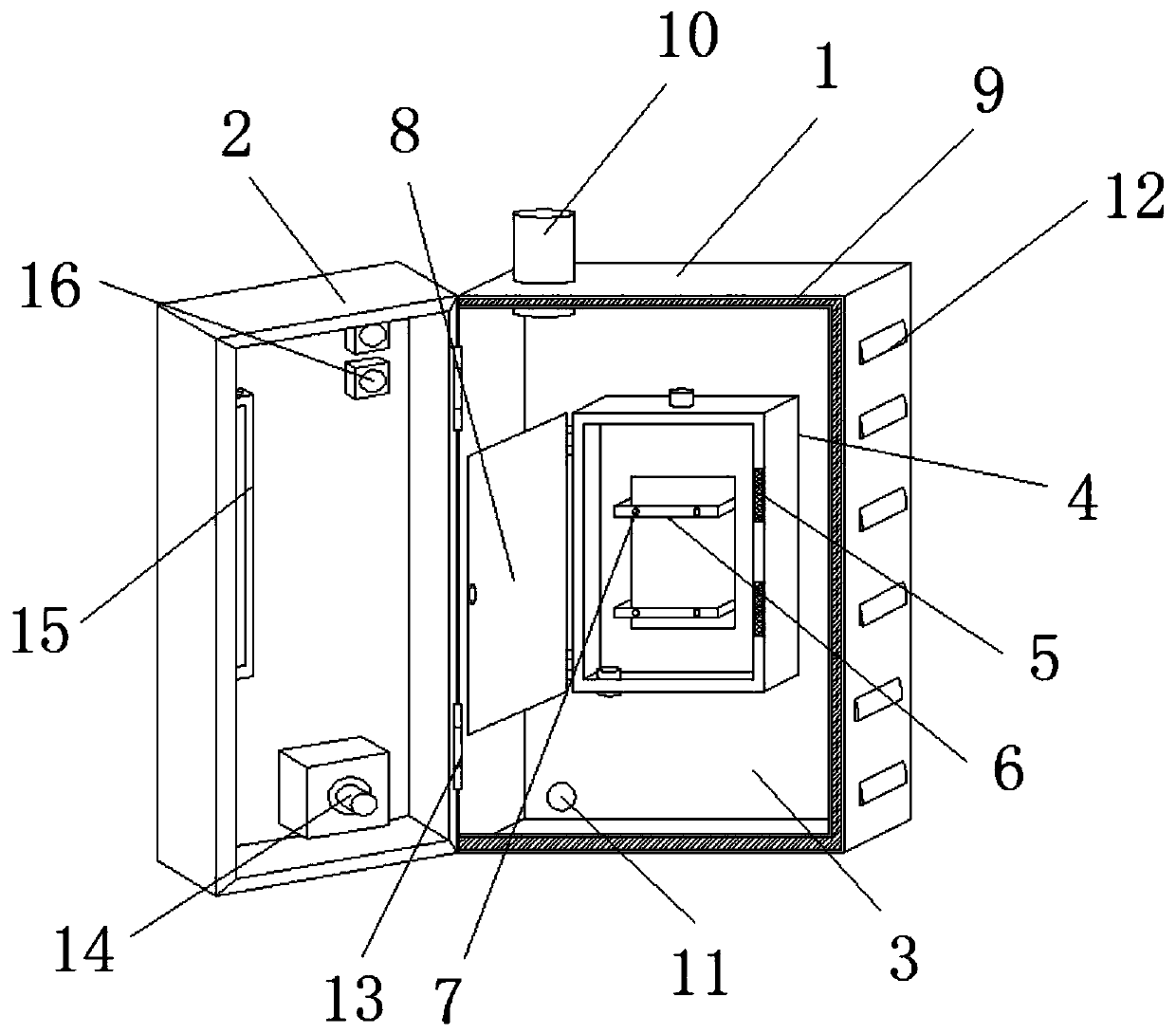
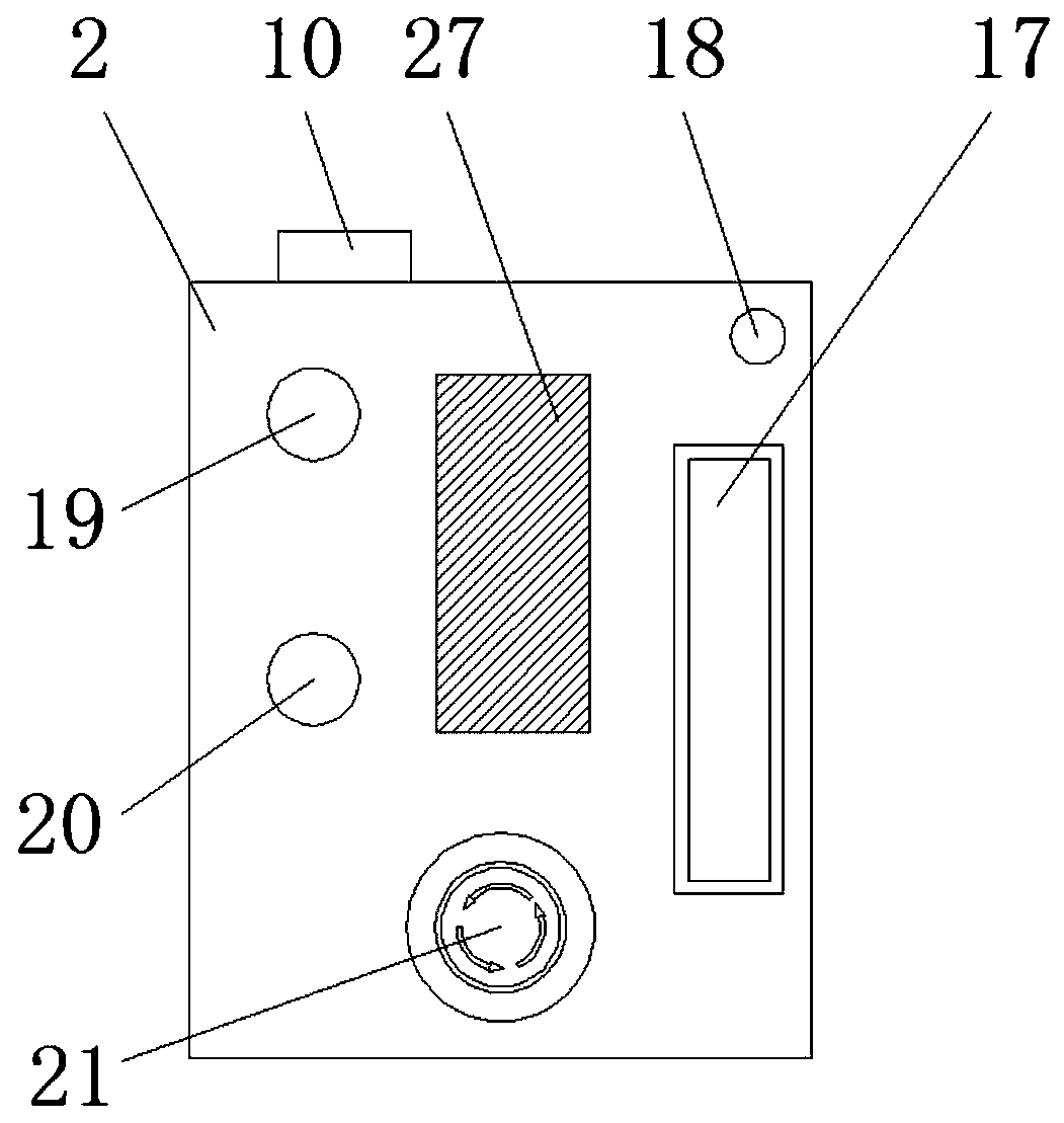
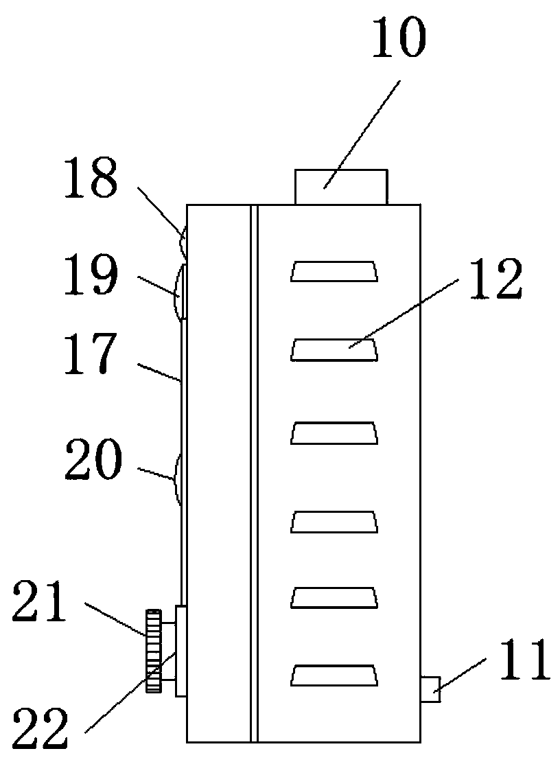
[0018] see Figure 1-4 , the present invention provides a technical solution: an emergency stop device triggered by smart industry, including an emergency stop device chassis 1, the left side of the upper end of the emergency stop device chassis 1 is provided with a cabinet wire outlet 10, and the outside of the emergency stop device chassis 1 is provided with The cooling port 12 of the chassis, the outer side of the lower end of the emergency stop device chassis


PUM


Abstract

The invention discloses a smart industry triggering emergency stop device which comprises an emergency stop device chassis. The left side of the upper end of the emergency stop device chassis is provided with a chassis wire outlet. A chassis heat dissipation port is arranged in the outer side of the emergency stop device chassis. A chassis wire inlet is clamped on the outer side of the lower end of the emergency stop device chassis. A chassis chamber is arranged inside the emergency stop device chassis. A reset spring is movably connected between a clamp fixed wheel and an emergency stop button. A signal output block is fixedly arranged on the west section of a switch connecting seat. An emergency stop switch connecting joint is fixedly arranged on the tail end of an emergency stop buttonbase. A fault indicator light is fixedly arranged on the upper end of the left side of a protective box cover. An alarm indicator light is fixed arranged on the lower end of the fault indicator light.The smart industry triggering emergency stop device can better help an operator to make the use state and fault repair of a device more convenient, and also enables the emergency stop device to moreprecisely control the device.

Description


Claims


Application Information

Patent Timeline
Owner GANZHOU XIKE ENERGY SAVING AUTOMATION EQUIP CO LTD
Why Eureka
Try Eureka