Device and technology for flue gas desulfurization through soda ash method

A desulfurization device and flue gas technology, which is applied in the field of soda ash flue gas desulfurization, can solve the problems of high energy consumption of circulating pumps, complex devices, and high content of flue gas particles, and achieve the goal of reducing the cost of alkali, reducing the cost of desulfurization, and high emission concentration Effect

Pending Publication Date: 2019-11-12
大连汉诺工程技术有限公司
View PDF1 Cites 7 Cited by
  • Summary
  • Abstract
  • Description
  • Claims
  • Application Information

AI Technical Summary

Benefits of technology

This new type of treatment process uses both acidic solutions (sprayed) or bases like caustic soda), which are effective at removing sulfur from wastewater before it reaches landfills without causing environmental concerns such as air pollution issues associated therewith. It also involves separating these treatments by different levels based on their efficiency towards specific contaminants that require removal. Overall this innovation helps reduce costs while maintaining safe and stable operation over large geographies where disposal methods have been developed.

Problems solved by technology

This patents describes different ways to remove sulfur dioxides (SO2) emitted during coal burning operations without adding expensive chemicals like caustic solution. These techniques involve either injecting water into an exhaust system with a specific design feature called Spout Vacuum Desulphrator (SVDD) or another similar technology. Another option involves replacing existing equipment altogether through a more complex procedure involving multiple steps including acid precipitation followed by neutralizing them beforehand.

Method used


Image

  • Device and technology for flue gas desulfurization through soda ash method
  • Device and technology for flue gas desulfurization through soda ash method

Examples


Embodiment 1

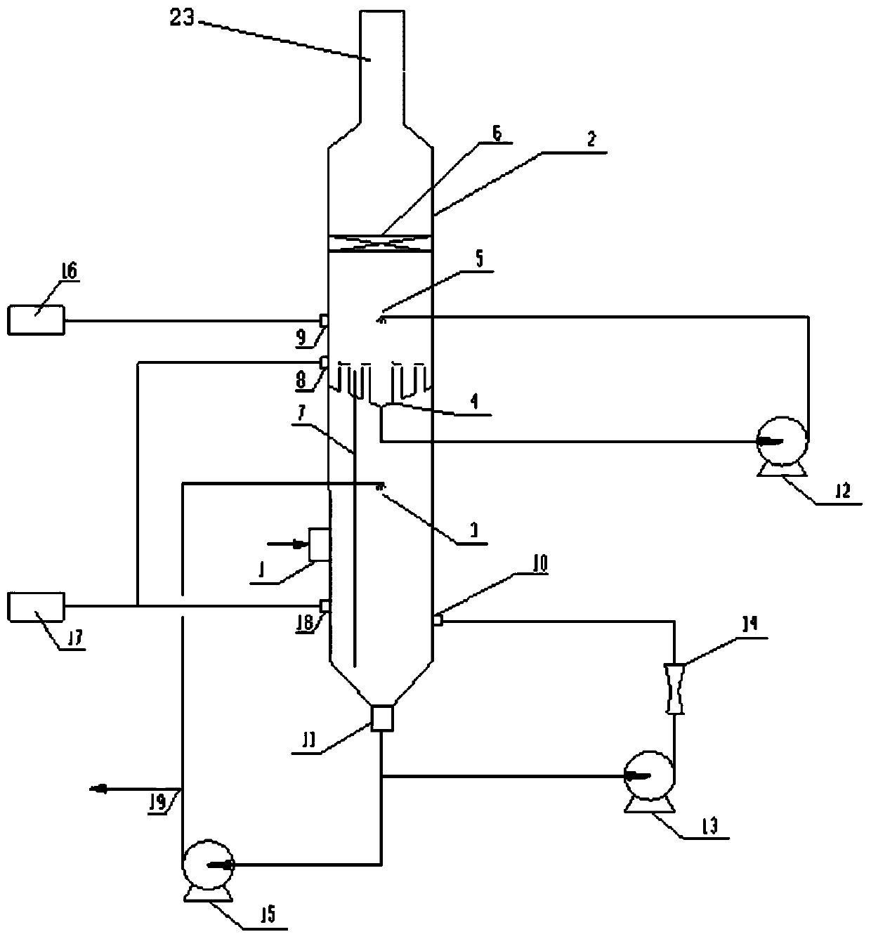
[0028] Such as figure 1 As shown, it is a structural schematic diagram of the technical solution of the empty tower spray pretreatment system. The specific implementation method adopts the following technical solution: including flue gas inlet 1, desulfurization tower 2, quenching nozzle 3, liquid collection tank 4, spray nozzle 5, desulfurization Mister 6, liquid level connecting pipe 7, second lye inlet 8, fresh water inlet 9, tower kettle side wall gas-liquid inlet 10, washing liquid outlet 11, washing circulation pump 12, oxidation circulation pump 13, oxidation jet nozzle 14 , quenching circulation pump 15, process water conveying system 16, sodium carbonate preparation system 17, first lye inlet 18, drain outlet 19, chimney 23; chimney 23 is arranged at the top of desulfurization tower 2, and washing liquid outlet 11 is arranged at the bottom of desulfurization tower , the mist eliminator 6 is located inside the desulfurization tower 2 and is located below the chimney 23;

Embodiment 2

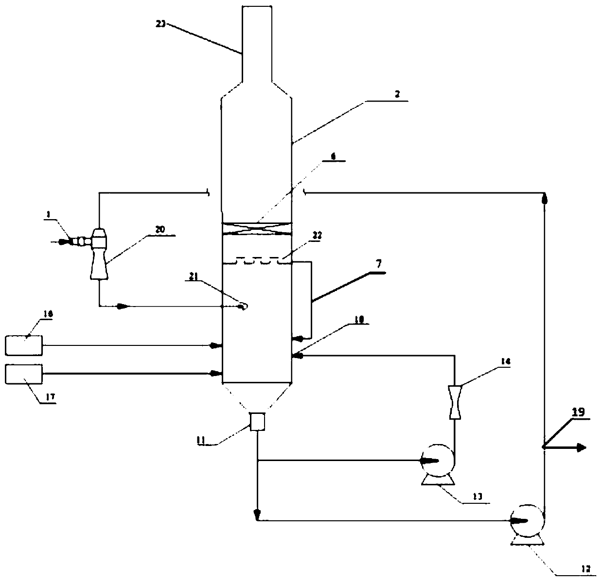
[0038] Such as figure 2 As shown, it is a structural schematic diagram of the technical solution of the spraying Venturi pretreatment system. This specific embodiment adopts the following technical solution: including flue gas inlet 1, desulfurization tower 2, demister 6, tower kettle side wall gas-liquid inlet 10, washing Liquid outlet 11, washing circulation pump 12, oxidation circulation pump 13, oxidation jet nozzle 14, process water delivery system 16, sodium carbonate preparation system 17, water outlet 19, high-energy Venturi injector 20, gas-liquid inlet 21, gas distribution plate 22; The top of the desulfurization tower 2 is provided with a chimney 23, the bottom of the desulfurization tower is provided with a washing liquid outlet 11, and the demister 6 is located inside the desulfurization tower 2, located below the chimney 23;

[0039] The flue gas inlet 1 is the gas phase inlet of the high-energy Venturi injector 20; the gas-liquid inlet 21 is located inside the des


PUM

PropertyMeasurementUnit
Particle sizeaaaaaaaaaa

Abstract

The invention provides a device for flue gas desulfurization through a soda ash method. The device is characterized in that the device comprises a pretreating system used for dissolving SO2 in liquid-phase water, a desulfurization tower, a technological water delivering system, a sodium carbonate preparing system used for providing alkali liquor, and an oxidation cycle system used for oxidizing sodium sulfite; a chimney is arranged at the top of the desulfurization tower, a demister is arranged on the lower part of the chimney, the desulfurization tower is connected with the technological water delivering system and the sodium carbonate preparing system, a tower kettle side wall gas-liquid inlet is formed in the tower kettle position of the desulfurization tower, a washing liquid outlet isformed in the bottom of the desulfurization tower, and the washing liquid outlet is connected with the tower kettle side wall gas-liquid inlet through the oxidation cycle system; and the pretreatingsystem is a Venturi pretreating system or an empty tower spraying pretreating system. According to the device, the alkali using cost is obviously lowered, safety and stability of a desulfurization technique are achieved, economical efficiency is achieved, and the device is suitable for application and promotion.

Description


Claims


Application Information

Patent Timeline
Owner 大连汉诺工程技术有限公司
Why Eureka
Try Eureka