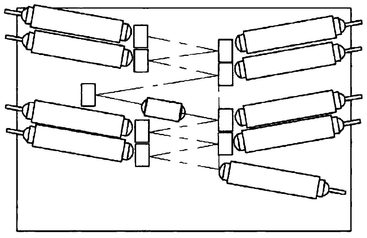
Multichannel wavelength division multiplexer

A wavelength division multiplexer and multi-channel technology, applied in the field of optical communication, can solve problems such as increased insertion loss, limited transmission distance, and increased device cost

Inactive Publication Date: 2019-11-29
珠海市杰威光电科技有限公司
View PDF5 Cites 0 Cited by
  • Summary
  • Abstract
  • Description
  • Claims
  • Application Information

AI Technical Summary

Problems solved by technology

However, with the extension of the propagation distance, the diameter of the signal beam spot will expand, which limits the transmission distance; and the existing thin-film filter has a thick coating, and the naturally formed surface tension makes its microscopic upper surface It is a convex surface, which further exacerbates the expansion of the spot diameter of the signal beam
The signal beam inside the wavelength division multiplexer will undergo multiple reflections. Every time it is reflected by the thin film filter, the beam will be expanded once. The enlarged spot will make it difficult f

Method used


Image

  • Multichannel wavelength division multiplexer
  • Multichannel wavelength division multiplexer
  • Multichannel wavelength division multiplexer

Examples


Embodiment Construction

[0028] The specific embodiments of the present invention will be further described below in conjunction with the accompanying drawings. It should be noted here that the descriptions of these embodiments are used to help understand the present invention, but are not intended to limit the present invention. In addition, the technical features involved in the various embodiments of the present invention described below may be combined with each other as long as they do not constitute a conflict with each other.

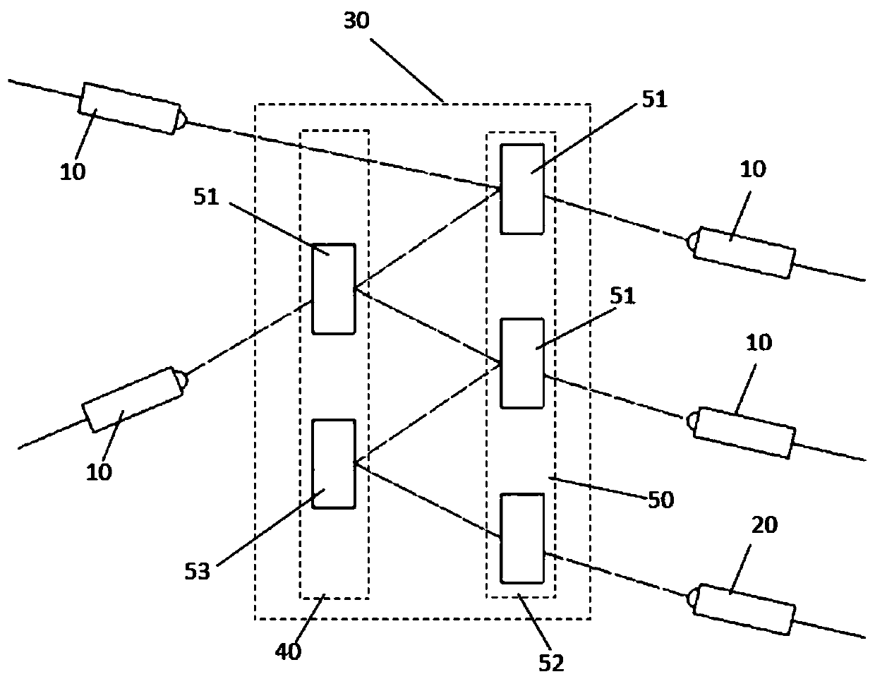
[0029] A multi-channel wavelength division multiplexer, such as figure 1 As shown, several first collimators 10, several second collimators 20 and refraction layers 30 are included;

[0030] The refraction layer 30 is arranged between the first collimator 10 and the second collimator 20;

[0031] Among them, such as figure 1 As shown, the refraction layer 30 includes a left refraction layer 40 and a right refraction layer 50, the inside of the right refraction layer 50 i


PUM


Abstract

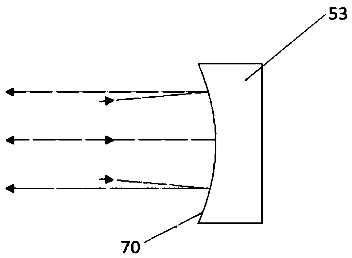
The invention provides a multichannel wavelength division multiplexer which comprises first collimators, second collimators and a refraction layer. The refraction layer is arranged between the first collimators and the second collimators; the refraction layer further comprises a left refraction layer and a right refraction layer; first film filters and second film filters are arranged in the rightrefraction layer; and first film filters and a high-reflectivity mirror are arranged in the left refraction layer. According to the multichannel wavelength division multiplexer in the above the structure, signal light beams reflected by the first or second film filters are shaped by arranging the high-reflectivity mirror, so that the signal light beams are clustered again and can be spread further; and therefore, the size of a light spot can be completely received by the subsequent collimators, and the purposes of low loss and long working distance are achieved.

Description


Claims


Application Information

Patent Timeline
Owner 珠海市杰威光电科技有限公司
Why Eureka
Try Eureka