Light emitting assembly and optical module using same

A technology for optical emission components and optical modules, applied in the field of optical communication, can solve the problems of complex emission components and complex assembly, and achieve the effect of simplifying the assembly process, reducing material costs, and saving carrier boards.

Pending Publication Date: 2021-06-11
光彩芯辰(浙江)科技有限公司
View PDF10 Cites 0 Cited by
  • Summary
  • Abstract
  • Description
  • Claims
  • Application Information

AI Technical Summary

Benefits of technology

This new design allows for easy mounting of an LED (light emitter) package onto any type of surface without requiring extra materials or steps like adding carriers between different parts that make up the entire device.

Problems solved by technology

This patented describes an issue where high performance computing devices require very expensive equipment due to their limited resources available at once. To address this problem, many companies now offer offshore facilities called OpGen® located near coasts worldwide. These facilities use powerful computers but they face challenges like increasing costs associated with maintaining these systems over longer periods of time. Additionally, some organizations may only allow access within certain areas without requiring advanced technology capabilities. Overall, the challenge presented needs to reduce expense while improving efficiency in producing highly efficient opticals needed for future applications.

Method used


Image

  • Light emitting assembly and optical module using same
  • Light emitting assembly and optical module using same
  • Light emitting assembly and optical module using same

Examples


Embodiment Construction

[0027] The present invention will be described in further detail below in conjunction with the accompanying drawings.

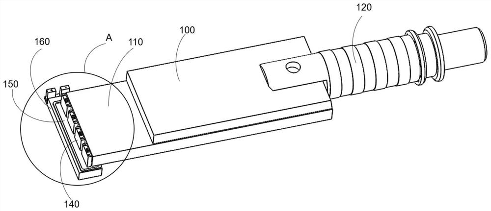
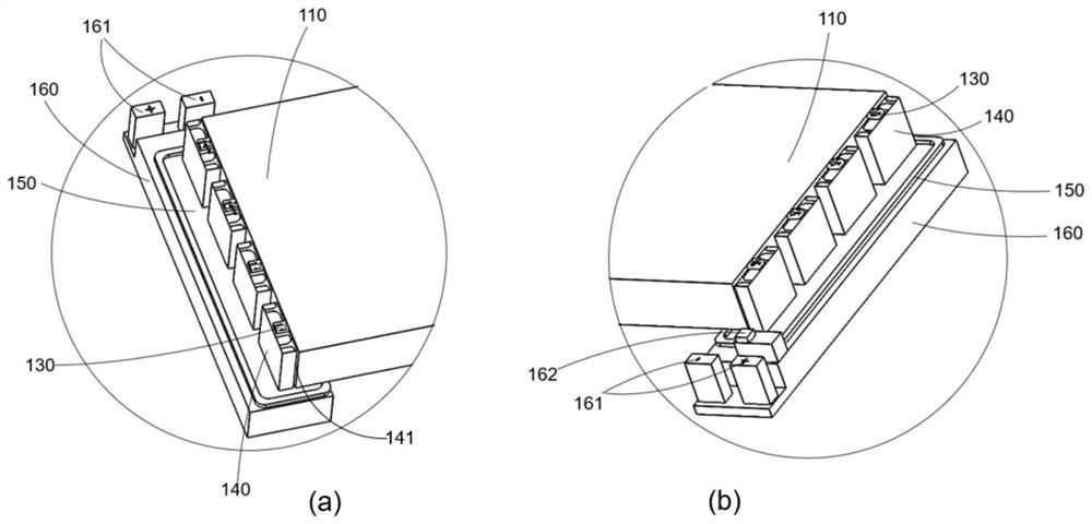
[0028] figure 1 Schematically shows the structure of a light emitting assembly according to an embodiment of the present invention, figure 2 then it shows figure 1 The structure of region A in which figure 2 (a) and figure 2 (b) Area A is shown in more detail from two opposite sides, respectively. like Figure 1-2 As shown, the light emitting component 100 includes a wavelength division multiplexing element (MUX) 110 , a light emitting port 120 and devices in area A.

[0029] In area A, it can be obtained that the light-emitting component 100 further includes a plurality of lasers 130, a plurality of heat dissipation pads 140 corresponding to each laser 130, a heat conduction silicone grease 150 located under the heat dissipation spacers 140, a heat conduction silicone grease 150 located under the heat conduction silicone grease 150 The thermoelectric c


PUM


Abstract

The invention discloses a light emitting assembly and an optical module using the same. The light emitting assembly comprises a wavelength division multiplexing element, a light emitting port, a plurality of lasers and a thermoelectric refrigerating unit, wherein the light emitting port and the lasers are located at the two ends of the wavelength division multiplexing element respectively, and the lasers are installed on the thermoelectric refrigerating unit; one side of the wavelength division multiplexing element is provided with a plurality of optical input ports, the other side of the wavelength division multiplexing element is provided with an output port, the optical input ports correspond to the lasers respectively, and the output port corresponds to the light emitting port. According to the light emitting assembly, by designing the structural composition and position of each component, each component can be directly mounted on the tube shell base when forming the light module, so that a carrier plate playing a role in bearing is saved, the material cost of the optical module is reduced, and meanwhile, the assembly process of the optical module is simplified.

Description


Claims


Application Information

Patent Timeline
Owner 光彩芯辰(浙江)科技有限公司
Why Eureka
Try Eureka