Tool for closing in plunger assembly and machining method

An assembly and column alignment technology, which is applied in the field of tooling and processing for closing the plunger assembly, can solve the problems of permanent damage to the assembly, fluctuations in the product qualification rate, and dependence on the processing qualification rate, and achieves good consistency and flexible closing deformation. Control and avoid the effect of cutting edge effect

Inactive Publication Date: 2019-12-13
JINCHENG NANJING ELECTROMECHANICAL HYDRAULIC PRESSURE ENG RES CENT AVIATION IND OF CHINA
View PDF10 Cites 2 Cited by
  • Summary
  • Abstract
  • Description
  • Claims
  • Application Information

AI Technical Summary

Benefits of technology

This patented technology allows for quick removal or replacement of both openings on two slipper shoes without affecting their functionality. Additionally, it provides stable and reliable lock structures with internal holes that prevent accidental changes when inserting tools into them while still providing strong grip between parts. These technical improvements improve process efficacy and quality control over closed-form workpieces produced through this method.

Problems solved by technology

The technical problem addressed in this patented text relates to reducing defects during closed-end processes for producing pistons with improved quality control rates due to changes made over time caused by changing material properties or manufacturing techniques such as lasers cutting through metal threads.

Method used


Image

  • Tool for closing in plunger assembly and machining method
  • Tool for closing in plunger assembly and machining method
  • Tool for closing in plunger assembly and machining method

Examples


Embodiment Construction

[0023] In order to better illustrate the present invention, it will be described in detail below in conjunction with the accompanying drawings.

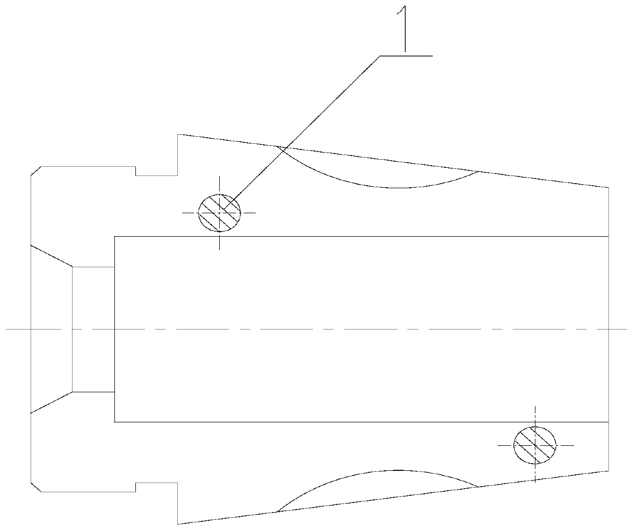
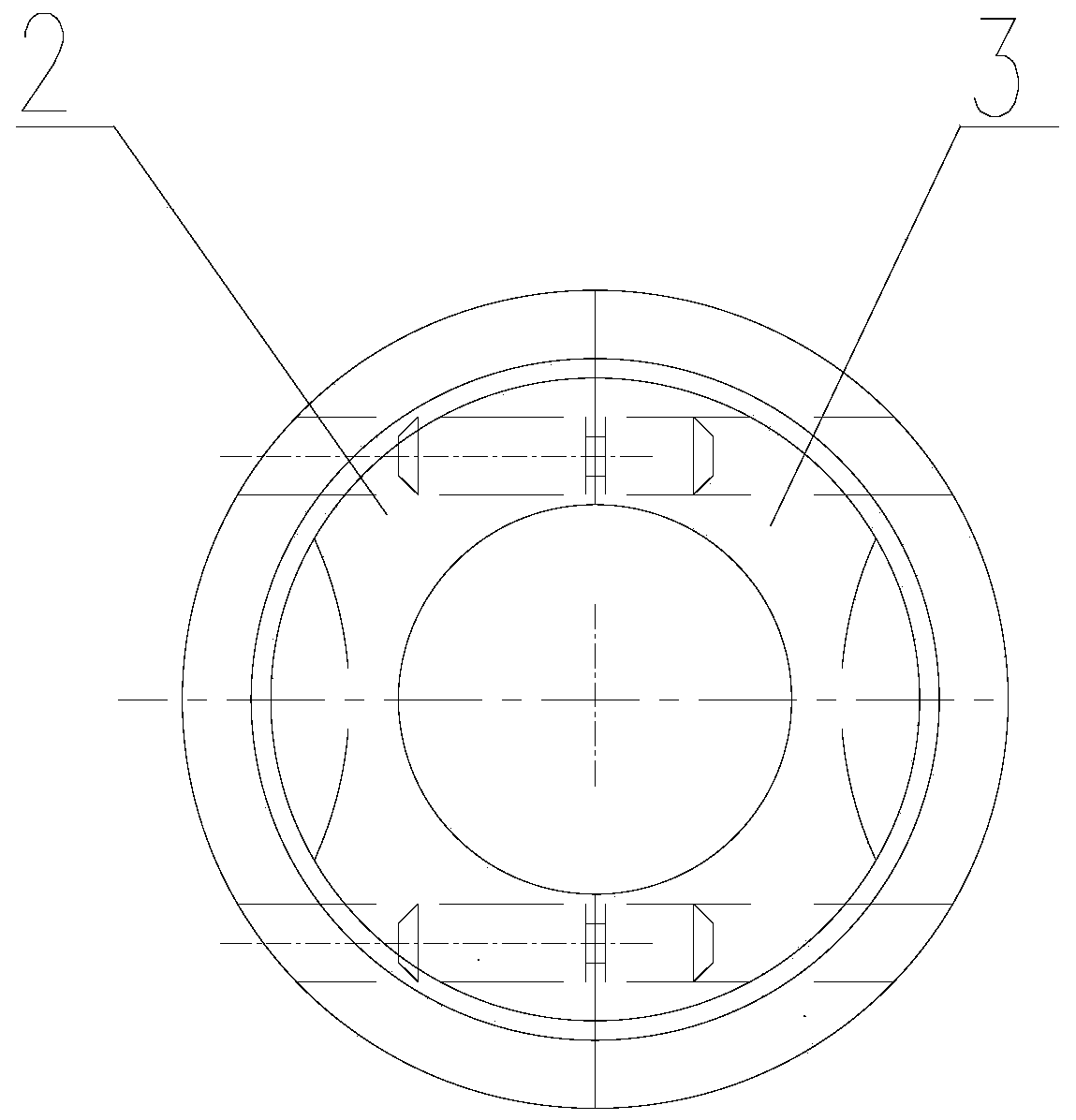
[0024] see figure 1 , figure 2 , is the structure diagram of the plunger assembly for closing processing, including sliding pin 1, left split sleeve 2, and right split sleeve 3;

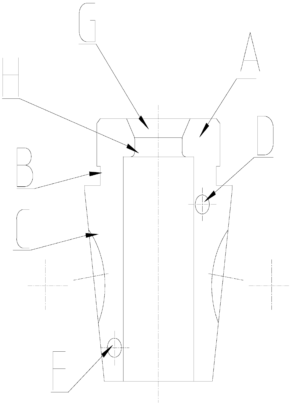
[0025] Such as image 3 Shown is the structure of left split sleeve 2, right split sleeve 3. The left open sleeve 2 and the right open sleeve 3 are both semi-revolving structures, which are combined into a revolving structure. The revolving structure is divided into two parts, which are cylinder A, semi-conical frustum C, and the diameter of cylinder A Smaller than the diameter of the connecting surface between the semi-conical frustum C and the cylinder A, the cylinder A is provided with a cylindrical hole H and a cylindrical hole J in turn, and the semi-conical frustum C of the rotary structure is provided with an asymmetric through cylindrical hole D an


PUM


Abstract

The invention belongs to the field of machining, and particularly relates to a tool for closing in a plunger assembly and a closing-in method. The tool comprises sliding pins (1), a left opening sleeve (2) and a right opening sleeve (3). The tool is connected with the left opening sleeve (2) and the right opening sleeve (3) through the sliding pins (1) to form an inner conical hole, and the closing-in machining requirement is met by means of the step size shrinkage of the inner conical hole; and meanwhile, the edge cutting problem caused by impact load during machining of closing-in type products is solved, and the consistency of the overall machining quality of the products is guaranteed.

Description


Claims


Application Information

Patent Timeline
Owner JINCHENG NANJING ELECTROMECHANICAL HYDRAULIC PRESSURE ENG RES CENT AVIATION IND OF CHINA
Why Eureka
Try Eureka