Padding device for textile fabrics

A technology for textile fabrics and padding, which is applied in the processing of textile materials, processing textile material drums, and processing textile material carriers, etc. The consumption of water and heat energy, the effect of reducing the residual ratio

Inactive Publication Date: 2019-12-13
李筱穗
View PDF0 Cites 4 Cited by
  • Summary
  • Abstract
  • Description
  • Claims
  • Application Information

AI Technical Summary

Problems solved by technology

[0003] During the use of the existing padding machine, the distance between the upper roll and the lower roll remains unchanged. When it is used for a long time, the surfaces of the upper roll and the lower roll are easy to cause wear, and because each time it works, the padding fabric The material and thickness are not necessarily exactly the same, which is likely to cause an increase in the excess rate, and each time the rolled fabric passes the upper roll and the lower roll, most of the rolling liquid contained in the squeezed part of the rolled fabric instantly flows into the rolled fabric. The movement of the left and right sides will easily cause the position of the internal material of the padding fabric to change, and at the same time cause the padding liquid to splash around, which is not conducive to the recycling of the exhibition industry. Therefore, we propose a padding equipment for textile fabrics.

Method used


Image

  • Padding device for textile fabrics
  • Padding device for textile fabrics
  • Padding device for textile fabrics

Examples


Embodiment Construction

[0022] The following will clearly and completely describe the technical solutions in the embodiments of the present invention with reference to the accompanying drawings in the embodiments of the present invention. Obviously, the described embodiments are only some, not all, embodiments of the present invention. Based on the embodiments of the present invention, all other embodiments obtained by persons of ordinary skill in the art without making creative efforts belong to the protection scope of the present invention.

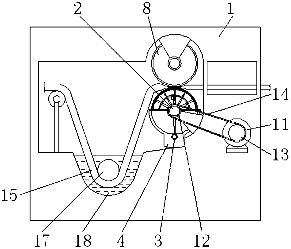
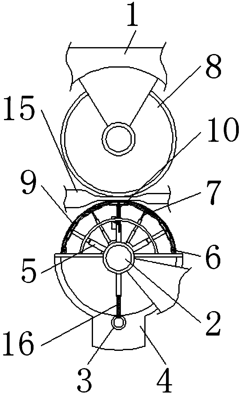
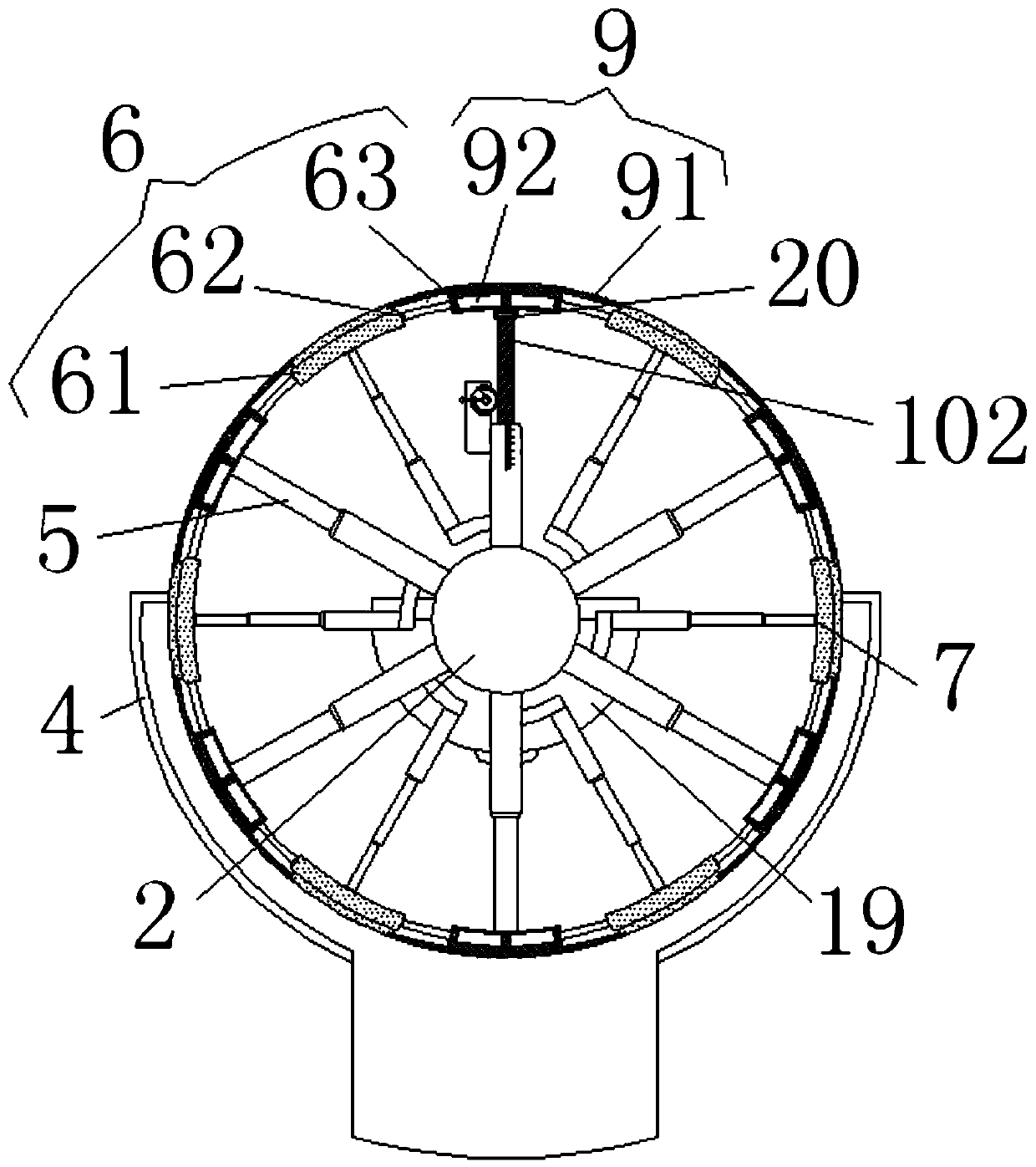
[0023] see Figure 1-5 , a kind of padding equipment for textile fabrics, comprising a padding frame 1, a control shaft 2 is movably socketed on the right side of the inner wall of the padding frame 1, a squeeze roller 3 is arranged at the bottom of the control shaft 2, and the top of the squeeze roll 3 A tightening rod 16 is movably socketed, and an arc-shaped liquid receiving bucket 4 is movably socketed on the lower surface of the control shaft 2, and an ad...


PUM


Abstract

The invention relates to the technical field of printing and dyeing processes and discloses a padding device for textile fabrics. The device comprises a padding frame, wherein a regulating shaft is movably sleeved on the right side of the inner wall of the padding frame; an extrusion roller is arranged at the bottom of the regulating shaft, and a tightening rod is movably sleeved on the top of theextrusion roller. According to the padding device for the textile fabrics, through the cooperation among a straight cylinder, a worm, a turbine and a rotating handle in a switch adjusting apparatus,the worm is clockwise rotated to move upwards, so that arc-shaped micropore linkage apparatuses are conveniently extended to the side far away from the regulating shaft, and redundant moisture on woven cloth which is subjected to dip rinsing is removed. Since micropores are formed in micropore regulating apparatuses and the arc-shaped micropore linkage apparatuses, moisture on a cloth guide rollercan conveniently flow out through the micropore regulating apparatuses and the arc-shaped micropore linkage apparatuses, so that the residual rolling rate of the padding device on the woven cloth isconveniently reduced, the consumption of water and heat energy is reduced, and the cyclic utilization of padding liquid in a padding liquid tank is facilitated.

Description

technical field [0001] The invention relates to the technical field of printing and dyeing technology, in particular to padding equipment for textile fabrics. Background technique [0002] Padding is a process of dip-dyeing cotton or polyester-cotton knitted fabrics with biological enzymes and pressing out the excess water in the dyed products. It belongs to the technical field of knitted fabric pretreatment in the printing and dyeing industry. The padding machine equipment is suitable for water-containing circular The drum fabric is subjected to padding and padding auxiliary treatment. The padding machine is often used as a device to remove excess water on the washed fabric before drying. [0003] During the use of the existing padding machine, the distance between the upper roll and the lower roll remains unchanged. When it is used for a long time, the surfaces of the upper roll and the lower roll are easy to cause wear, and because each time it works, the padding fabric ...

Claims


Application Information

Patent Timeline
IPC IPC(8): D06B3/18D06B15/02D06B23/02D06B23/04
CPCD06B3/18D06B15/02D06B23/025D06B23/042
Inventor 李筱穗
Owner 李筱穗
Why Eureka
Try Eureka