Engine bifurcated tail spray pipe weld joint laser shock peening and correcting method and device

A laser shock strengthening and laser shock technology, which is applied in the field of laser shock strengthening and shape correction of the welding seam of the engine bifurcated tail nozzle, can solve the problems such as the deformation of the tail nozzle, and achieve the effect of improving strength, ensuring stability and prolonging life

Active Publication Date: 2019-12-20
GUANGDONG UNIV OF TECH
View PDF5 Cites 1 Cited by
  • Summary
  • Abstract
  • Description
  • Claims
  • Application Information

AI Technical Summary

Benefits of technology

This technology allows for better control over how strong or stiffened certain parts are made from different materials like steel without causing damage during manufacture. Additionally it enables more accurate positioning of these components compared to previous methods that had limitations such as weaknesses at specific locations due to material properties. Overall this new process results in stronger and lighter structures while maintaining their durability.

Problems solved by technology

This patented technical problem addressed in this patents relating to the design and manufacture of improved diesel engines' rear end nozzles (referred to also referred to as tunnels) used at their ends can experience severe stresses while being driven without causing damaging failures such as crackings.

Method used

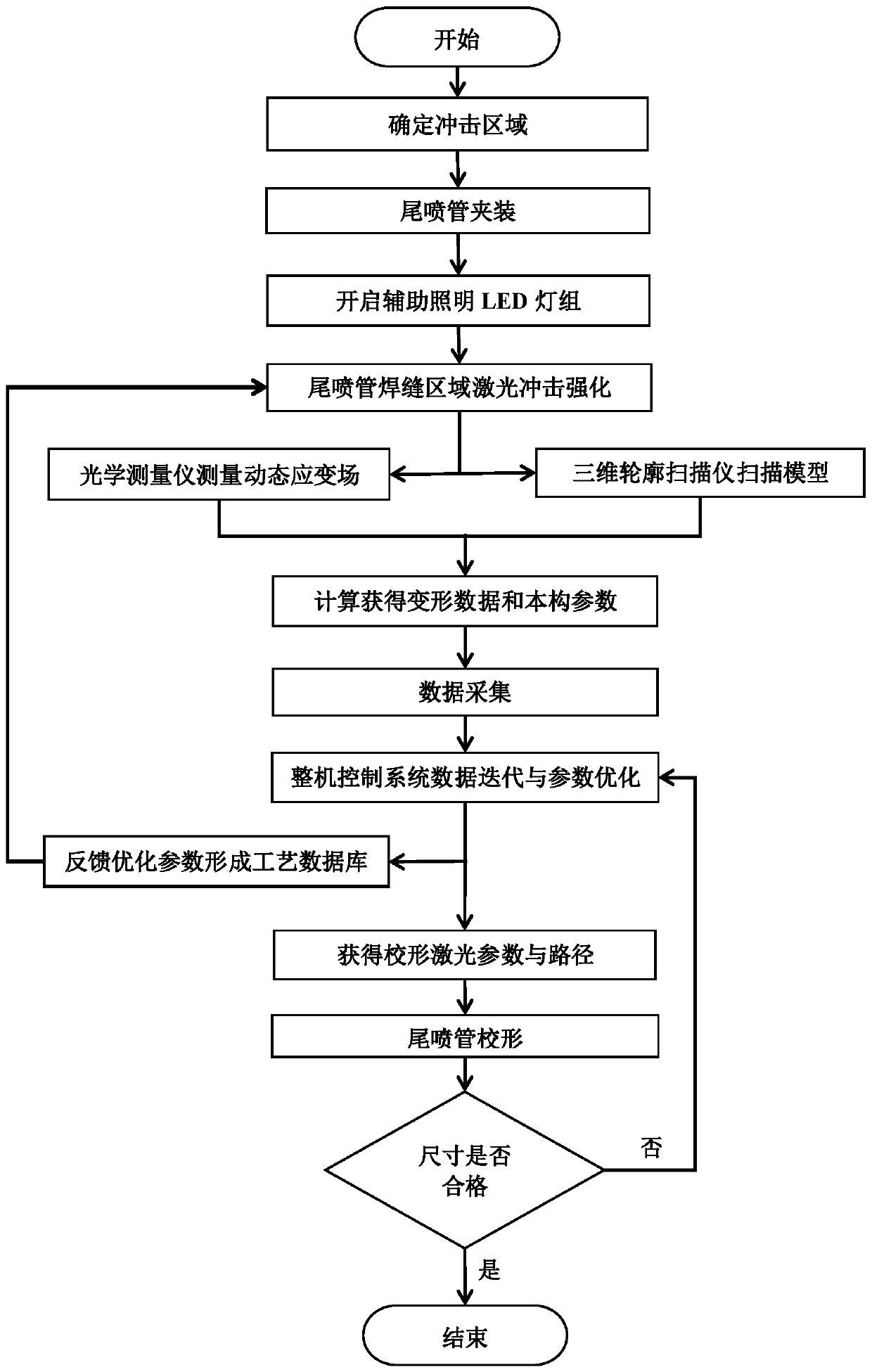
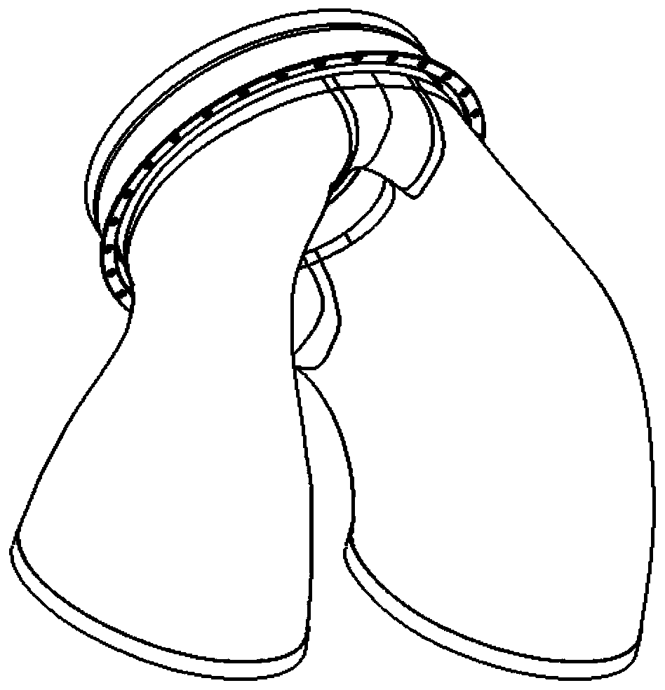

Image

  • Engine bifurcated tail spray pipe weld joint laser shock peening and correcting method and device
  • Engine bifurcated tail spray pipe weld joint laser shock peening and correcting method and device
  • Engine bifurcated tail spray pipe weld joint laser shock peening and correcting method and device

Examples


Embodiment 1

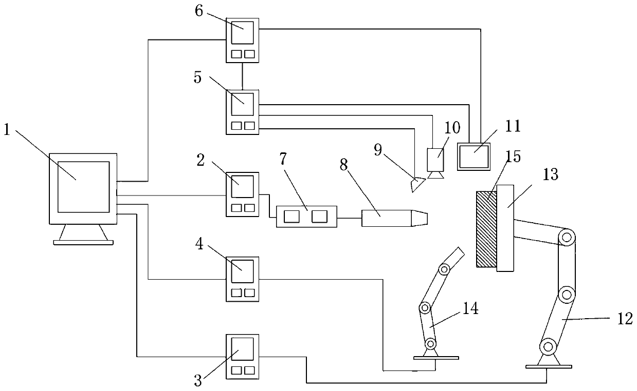
[0046] Such as figure 2 As shown, this embodiment discloses a device for laser shock strengthening and shape correction of the welding seam of the engine bifurcated tail nozzle. The device mainly includes a complete machine control system 1, a laser 7, a laser control system 2, and a laser shock strengthening unit 8. Auxiliary lighting LED lamp group 9. Special tooling fixture for tail nozzle 13. Clamping robot 12. Clamping robot control system 3. Watering robot 14. Watering robot control system 4. Optical measuring instrument 10. Optical equipment control system 5. Three-dimensional profile scanner 11, and data acquisition system 6;

[0047] Specifically, the whole machine control system 1 is respectively connected with the laser control system 2, the clamping robot control system 3, the water coating robot control system 4 and the data acquisition system 6, and drives each system to work together in an orderly manner; the optical device control System 5 is respectively connec


PUM


Abstract

The invention discloses an engine bifurcated tail spray pipe weld joint laser shock peening and correcting method and device. The method comprises the following steps: performing failure analysis on atail spray pipe, determining a weld joint area needing to perform laser shock peening, performing shock peening on the weld joint area needing to be peened by a laser shock peening unit according toa shock peening parameter of a thin-wall plate, measuring a material dynamic strain field of a laser shock peening area on line by virtue of an optical measuring instrument, calculating strain field data to acquire a material dynamic constitutive equation and dynamic strain rate data, aligning a tail spray pipe measuring model with a CAD model by virtue of a three-dimensional outline scanner, calculating curvature error and torsion error of a tail spray pipe reinforcement area, transmitting all the measured data to a whole machine control system, adjusting a laser parameter of shock peening and determining the laser parameter needing to be corrected and a correcting route, and correcting torsion and bending in the tail spray pipe reinforcement process through the laser shock peening unit.

Description


Claims


Application Information

Patent Timeline
Owner GUANGDONG UNIV OF TECH
Why Eureka
Try Eureka