Cleaning device for steel rail flaw detector

A cleaning device and flaw detector technology, which is applied in the field of flaw detectors, can solve the problems of affecting device detection, troublesome installation and disassembly, and low flexibility, so as to prevent hand slipping and reduce workload

Inactive Publication Date: 2019-12-20
宁波大桔科技有限公司
View PDF0 Cites 0 Cited by
  • Summary
  • Abstract
  • Description
  • Claims
  • Application Information

AI Technical Summary

Benefits of technology

This patented technology describes various technical improvements for detectors used along rails or guides (rail). These devices have handles attached to them through a lock ring, allowing users to easily attach these objects without having to hold down everything tightened while installing them. They are designed such that only necessary equipment like wires should come loose, reducing maintenance costs. Additionally, there is no risk of damage caused by sharp edges made against metal surfaces near the track area where the sensor operates. Overall, this innovation enhance safety measures and makes monitoring more efficient.

Problems solved by technology

The technical problem addressed by this patented technology relates to improving the efficiency with which an ultrasound flaw sensor operates without being affected by any external factors like sand, grit particles, dirt, debris from other parts of the machine's track, while also ensuring that no unnecessary maintenance needs to take place due to its flexibility.

Method used


Image

  • Cleaning device for steel rail flaw detector
  • Cleaning device for steel rail flaw detector
  • Cleaning device for steel rail flaw detector

Examples


Embodiment Construction

[0035] In order to make the object, technical solution and advantages of the present invention clearer, the present invention will be further described in detail below in conjunction with the accompanying drawings and embodiments. It should be understood that the specific embodiments described here are only used to explain the present invention, not to limit the present invention.

[0036] In the description of the present invention, it should be noted that the terms "center", "upper", "lower", "left", "right", "vertical", "horizontal", "inner", "outer" etc. The indicated orientation or positional relationship is based on the orientation or positional relationship shown in the drawings, and is only for the convenience of describing the present invention and simplifying the description, rather than indicating or implying that the referred device or element must have a specific orientation, or in a specific orientation. construction and operation, and therefore cannot be construed


PUM


Abstract

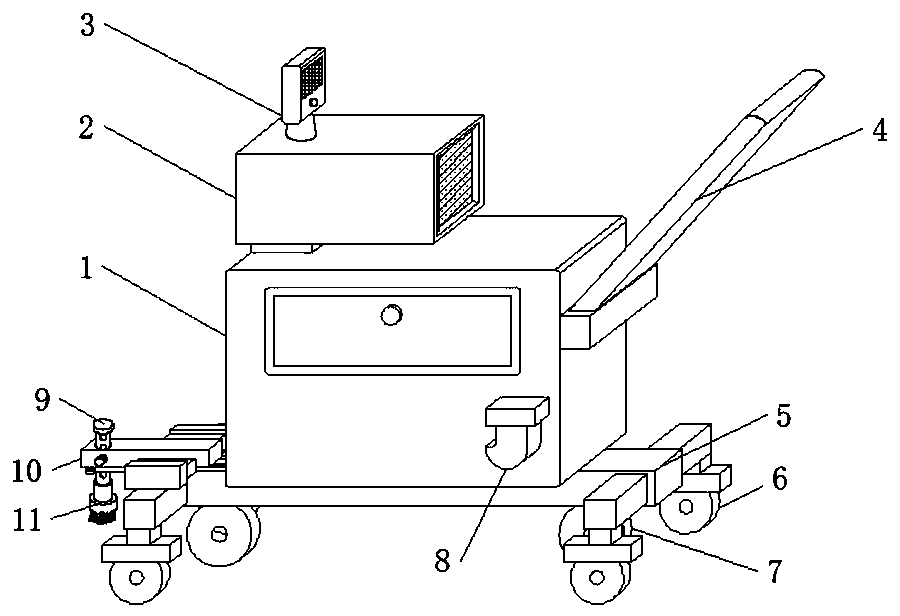
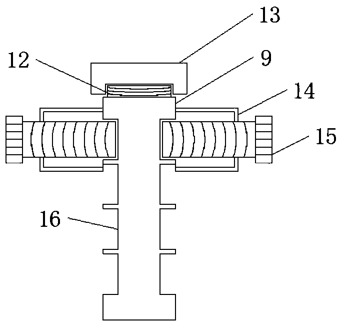
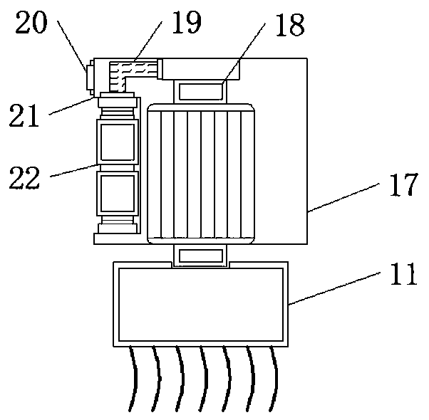
The invention discloses a cleaning device for a steel rail flaw detector. The cleaning device comprises a device main body, an ultrasonic detector and a bottom support, wherein the top of the device main body is fixedly connected with the ultrasonic detector; the top of the ultrasonic detector is fixedly connected with a data display screen; the bottom of the device main body is fixedly connectedwith the bottom support; one side of the bottom support is fixedly connected with a movable rail; the bottom of the bottom support is fixedly connected with a rail embedded wheel; the rear of the railembedded wheel is fixedly connected with a movable wheel; and the middle part of the movable rail is fixedly connected with the movable groove; the flexibility of the device main body is improved through the movable groove, the skid resistance of the device main body is improved through an anti-skid handle, a buffer cushion has a protective effect on the device main body, the convenience of the device main body is improved through a convenient mounting and dismounting mechanism, the applicability of the device main body is improved through a lifting mechanism, the detection precision of the device main body is improved through a cleaning mechanism, and the device is suitable for being used for cleaning in the rail flaw detector and has a wide development prospect in the future.

Description


Claims


Application Information

Patent Timeline
Owner 宁波大桔科技有限公司
Why Eureka
Try Eureka