Electric driver

A nail gun and nailing technology, applied in the field of nail guns, can solve the problem of difficulty in obtaining impact force, and achieve the effect of large friction force and high processing accuracy

Active Publication Date: 2009-09-09
MAKITA CORP
View PDF3 Cites 0 Cited by
  • Summary
  • Abstract
  • Description
  • Claims
  • Application Information

AI Technical Summary

Problems solved by technology

Even with the techniques disclosed in Patent Document 1 and Pate

Method used


Image

  • Electric driver
  • Electric driver
  • Electric driver

Examples


Embodiment Construction

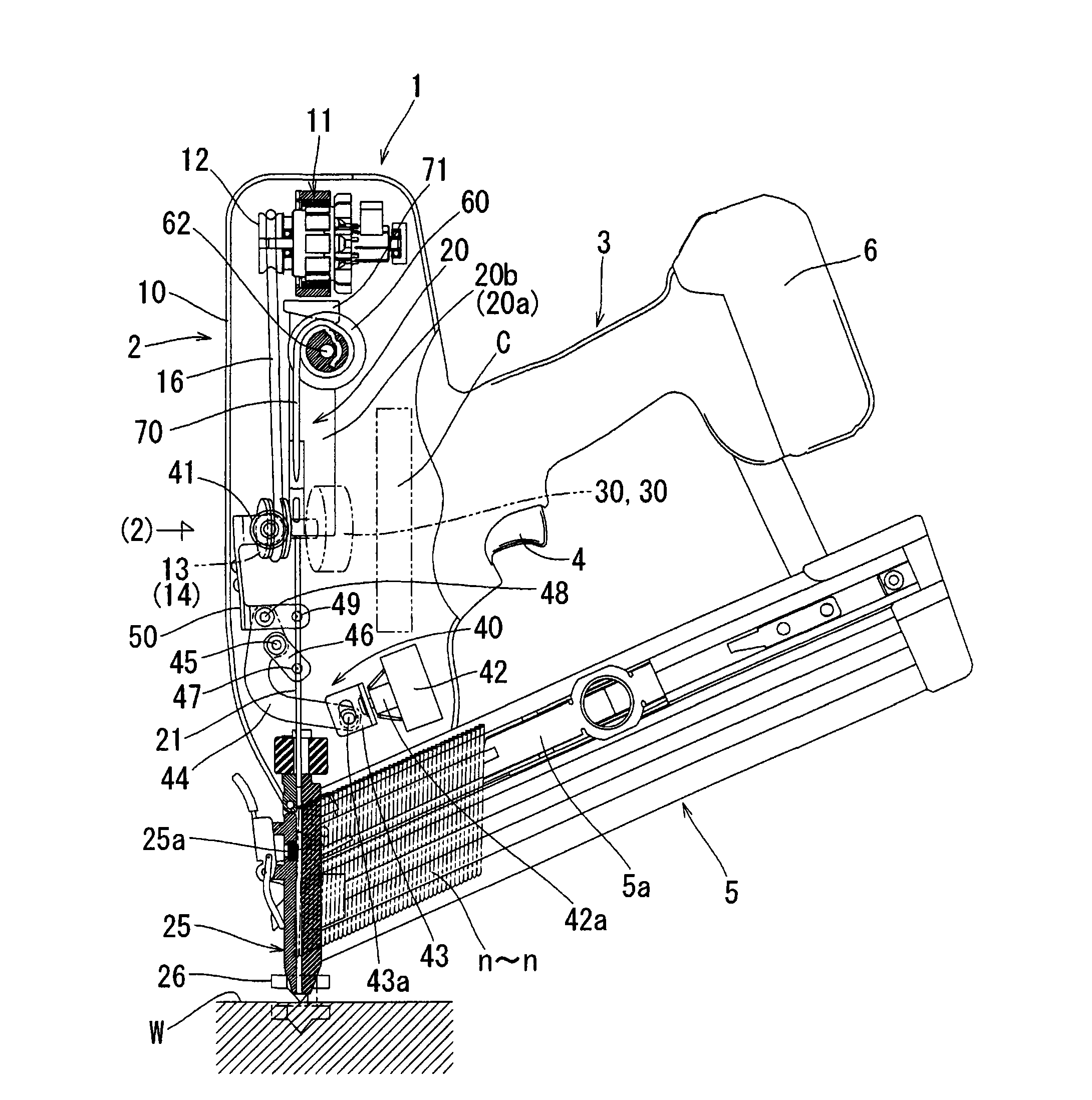
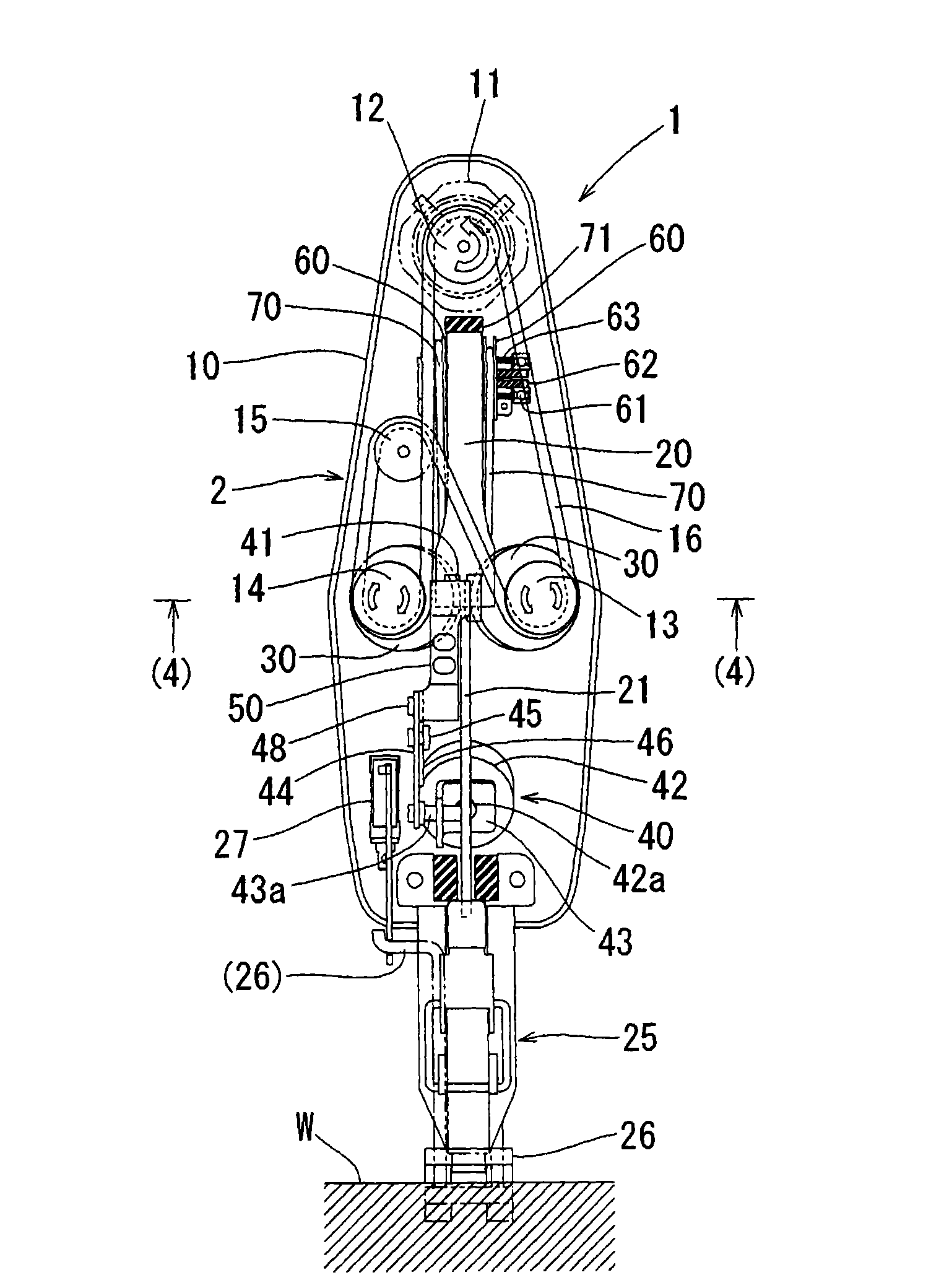
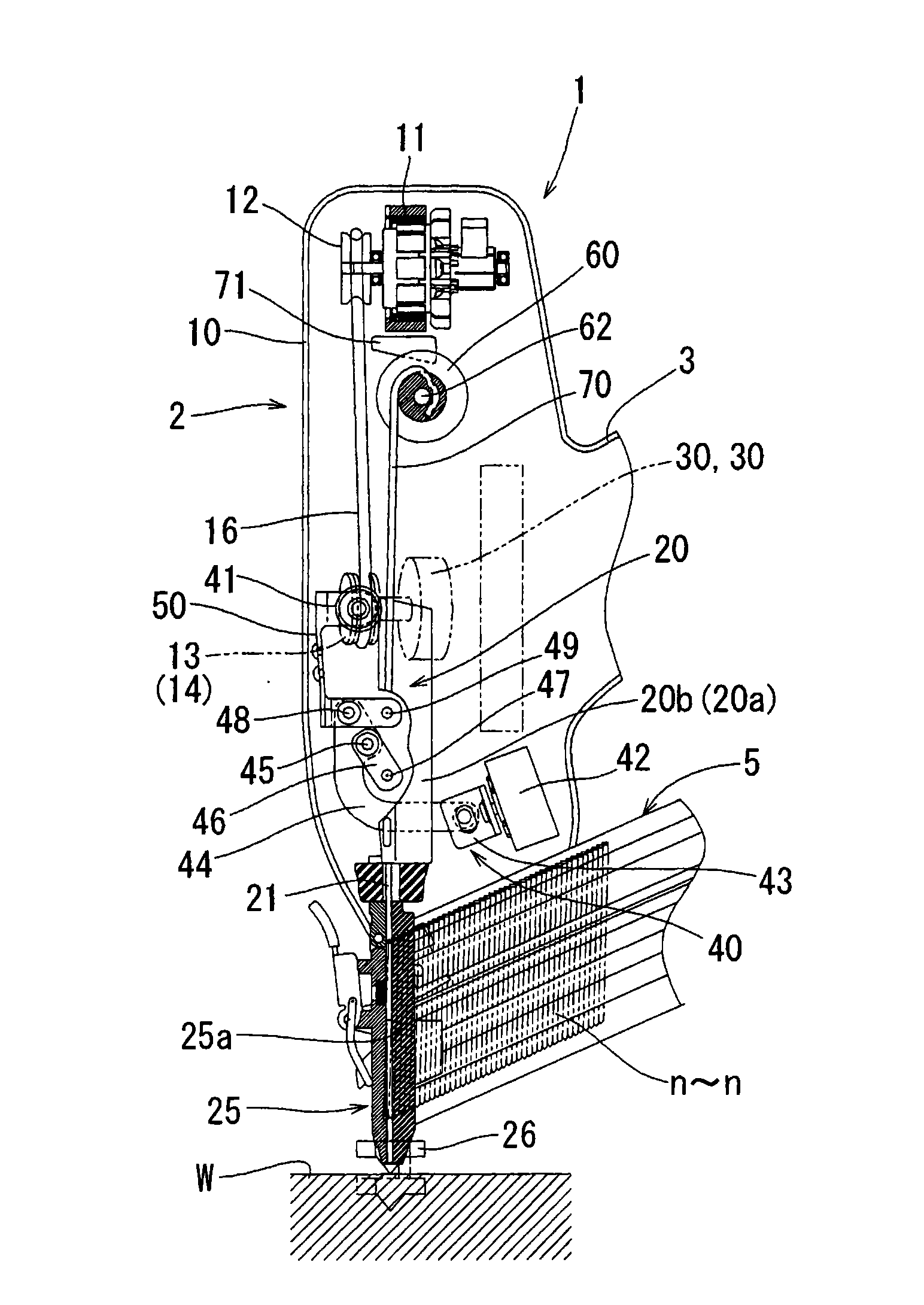
[0040] Below, refer to Figure 1 to Figure 17 Embodiments of the present invention will be described. Figure 1 ~ Figure 3The nail gun 1 of the first embodiment is shown. The nail gun 1 can be roughly divided into a body 2 and a handle 3 . The handle 3 is integrated with the body 2 and protrudes outward from the side of the body 2 . The base of the handle 3 is provided with a trigger switch lever 4 . A nail bin 5 is installed between the fuselage 2 and the handle 3, and the nail bin 5 is in a state spanning between the body 2 and the handle 3, and accommodates a plurality of nailing parts (a nail n is illustrated in this embodiment). ~n). The nail gun 1 of the present embodiment is characterized by a mechanism for driving a nail n which is a nail n. The handle 3 and the staple cartridge 5 are the same as the existing structures, and there is no special change in this embodiment, so the detailed description and illustration thereof are omitted.

[0041] figure 1 Indicates t


PUM


Abstract

Although in a driving tool operating by an electric motor as a drive source, according to a background art, there has been provided a technology of engaging projected streaks having V-shapes in cross sections with a plurality of V grooves in order to achieve a high striking force by efficiently transmitting a rotational force of a drive wheel to a driver support base, high working accuracy is needed in that case, and therefore, according to the invention, it is enable to achieve a large striking force without need of high working accuracy. A driver support base (20) is provided with a transmitting portion (20b) having a V-shape in cross section, the driver support base (20) is pressed by a press member (41) to cause the transmitting portion (20b) to wedge between a pair of left and right drive wheels (30, 30), so that a friction force is increased to achieved a large drive force of the driver support base (20).

Description


Claims


Application Information

Patent Timeline
Owner MAKITA CORP
Why Eureka
Try Eureka