Intelligent electrical automation control metal grinding machine
An automatic control and intelligent electrical technology, which is applied in the direction of engine components, engine lubrication, metal processing equipment, etc., can solve the problems of waste of coolant, no lubrication mechanism, low degree of automation, etc., to improve the degree of automation, save usage, The effect of improving machining accuracy
- Summary
- Abstract
- Description
- Claims
- Application Information
AI Technical Summary
Problems solved by technology
Method used
Image

Examples
Embodiment 1
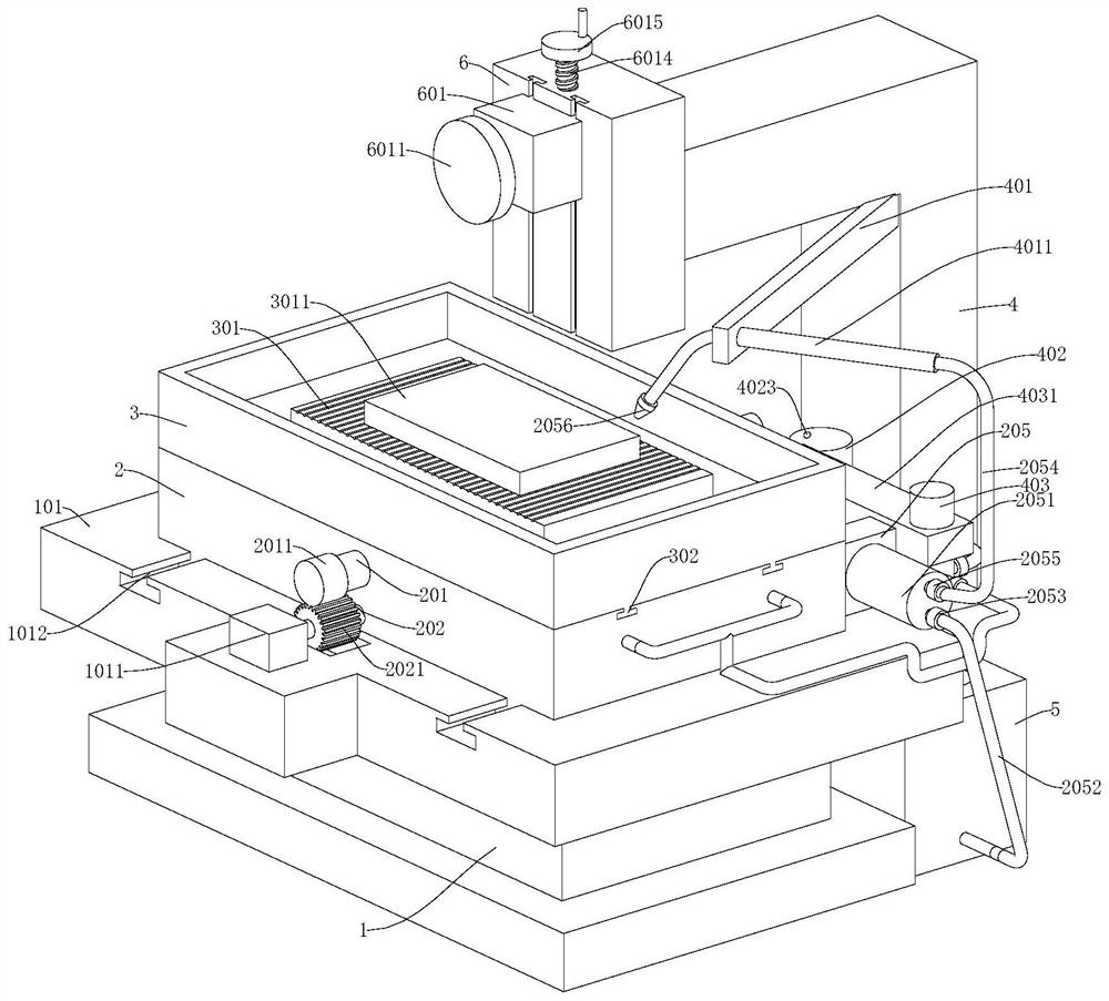
[0029] refer to Figure 1-7 , a metal grinding machine controlled by intelligent electrical automation, comprising a mounting base 1, a worktable 101 and a mounting beam 4 are fixedly connected to the mounting base 1, a first mounting platform 2 is slidably connected to the working platform 101, and the first mounting platform 2 The upper slide is connected with the second mounting table 3, the mounting beam 4 is fixedly connected with the mounting block 6, the mounting block 6 is slidingly connected with the first motor 601, and the output end of the first motor 601 is fixedly connected with the grinding wheel 6011, the first installation A cooling mechanism is provided on the platform 2, and a lubricating mechanism is provided on the mounting beam 4. After the first motor 601 is started, the grinding wheel 6011 starts to rotate, ready for grinding.
Embodiment 2
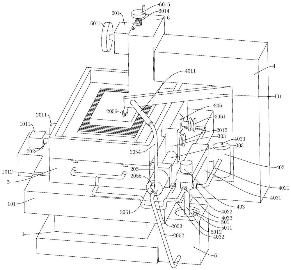
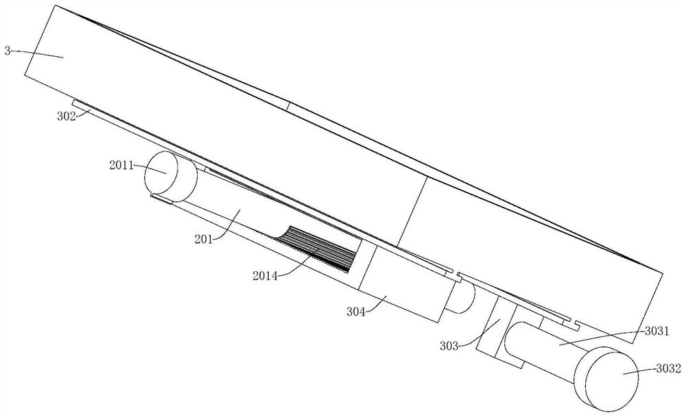
[0031] refer to Figure 1-7, which is basically the same as that of Embodiment 1, furthermore, a first chute 1012 is provided on the workbench 101, a first slider 203 is fixedly connected to the bottom of the first installation platform 2, and the first slider 203 is slidably connected to the first Inside the chute 1012, a screw rod 202 is threadedly connected to the first mounting table 2, and a rotating shaft 201 is rotatably connected to the first mounting table 2, and a single-tooth gear 2011 is coaxially fixedly connected to the rotating shaft 201, and the screw rod 202 is fixed coaxially A full-toothed gear 2021 is connected, and a bump 1011 is provided on the workbench 101. One end of the screw rod 202 located at the full-toothed gear 2021 is connected to the bump 1011 for fixed axis rotation, and one end of the rotating shaft 201 away from the full-toothed gear 2021 is fixedly connected with The driven wheel 2012 is fixedly connected with the second motor 206 on the first
Embodiment 3
[0034] refer to Figure 1-7 , is basically the same as that of Embodiment 1, and furthermore, the first motor 601 is fixedly connected with a third slider 6012 and a connecting block 6013, and the mounting block 6 is provided with a chute matching with the third slider 6012, and the connecting block Screw rod 6014 is threadedly connected on 6013, and screw rod 6014 is connected in the mounting block 6 in rotation, and the top of screw rod 6014 is coaxially fixedly connected with rotating disk 6015.
[0035] After the first motor 601 is started, the grinding wheel 6011 rotates. At this time, the rotating disk 6015 controls the screw rod 6014 to rotate clockwise or counterclockwise, thereby controlling the lifting of the first motor 601, thereby controlling the degree of grinding of the workpiece 3011.
PUM
 Abstract
Description
Claims
Application Information
 - R&D Engineer
- R&D Manager
- IP Professional
- Industry Leading Data Capabilities
- Powerful AI technology
- Patent DNA Extraction
Browse by: Latest US Patents, China's latest patents, Technical Efficacy Thesaurus, Application Domain, Technology Topic.
© 2024 PatSnap. All rights reserved.Legal|Privacy policy|Modern Slavery Act Transparency Statement|Sitemap