Transmission shaft support structure of sewing machine
A technology of supporting structure and transmission shaft, which is applied to sewing machine components, sewing machine control devices, sewing equipment, etc., can solve the problems of long transmission distance, affecting installation procedures, and high requirements for bushing flatness, achieving stable position and improving assembly accuracy. , The effect of low machining accuracy requirements
- Summary
- Abstract
- Description
- Claims
- Application Information
AI Technical Summary
Benefits of technology
Problems solved by technology
Method used
Image


Examples
Embodiment 1
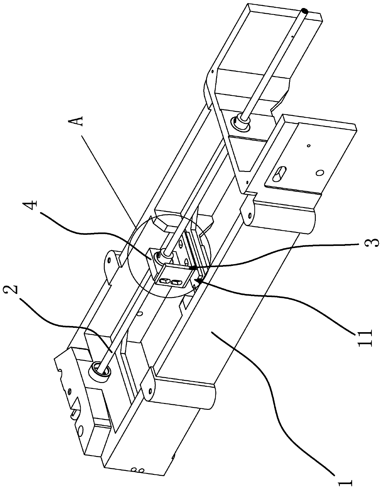
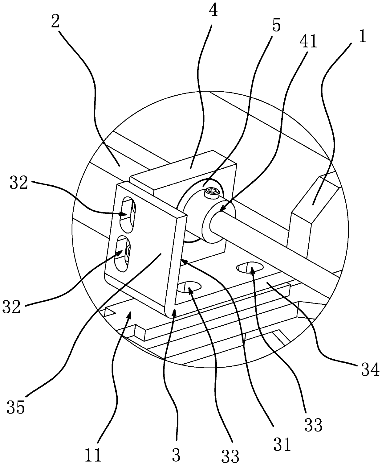
[0034] Such as Figure 1-6 As shown, the transmission shaft support structure of this sewing machine includes a frame 1 and a transmission shaft 2 extending in the front-to-back direction, and both ends of the transmission shaft 2 are rotatably connected to the frame 1. 11 is located below the middle section of the drive shaft 2, and the support surface 11 is detachably connected with a support frame 3 that can slide left and right along the support surface 11 and lock. The support frame 3 has an upwardly extending adjustment surface 31, which can be adjusted. The support block 4 is disassembled and connected to slide up and down along the adjustment surface 31 and locked. The support block 4 has a through hole 41 extending forward and backward. Frame 1 is an installation support platform for sewing machine components, and the two ends of the transmission shaft 2 extending forward and backward are rotatably connected to the frame 1. The rotation of the transmission shaft 2 can tr
Embodiment 2
[0036] Such as Figure 7 As shown, this embodiment is basically the same as Embodiment 1, the difference is that: the rear side edge of the riser 35 has two relief gaps 36 that allow the threaded joint 6 to move forward and backward. Corresponds to the position of the first adjustment hole 32 and communicates with the first adjustment hole 32 . By arranging two relief gaps 36 on the rear side edge of the vertical plate 35 that allow the threaded piece one 6 to move forward and backward, the relief gap 36 corresponds to the position of the adjustment hole one 32 and communicates with the adjustment hole one 32, and the two The distance between the gaps 36 is consistent with the distance between the two adjustment holes 32, so that the screw joint 6 can be pre-fitted with the support block 4 and screwed to a certain depth during assembly, and then the support block can be translated back and forth as a whole 4 Make the screw joint 6 enter the adjustment hole 32 from the gap 36, an
Embodiment 3
[0038] Such as Figure 8 As shown, this embodiment is basically the same as Embodiment 1, the difference is that the support frame 3 is U-shaped and includes a horizontal plate 34 and two vertical plates 35 perpendicular to the horizontal plate 34, and the horizontal plate 34 and the vertical plate 35 are all parallel to the axis line of the power transmission shaft 2, the support block 4 is located between the two vertical plates 35 and respectively abuts against the two vertical plates 35, the two adjustment holes 32 are respectively located on the two vertical plates 35, and the adjustment hole two 33 All are located on the horizontal plate 34. By arranging the support frame 3 in a U-shaped plate shape, the support block 4 is positioned between the two vertical plates 35 and abuts against the two vertical plates 35 respectively. They are all located on the horizontal plate 34, so that the left and right sides of the support block 4 can be sufficiently limited and supported, s
PUM
 Abstract
Description
Claims
Application Information
 - R&D Engineer
- R&D Manager
- IP Professional
- Industry Leading Data Capabilities
- Powerful AI technology
- Patent DNA Extraction
Browse by: Latest US Patents, China's latest patents, Technical Efficacy Thesaurus, Application Domain, Technology Topic.
© 2024 PatSnap. All rights reserved.Legal|Privacy policy|Modern Slavery Act Transparency Statement|Sitemap