Automatic resistor production equipment

A technology for automatic production and resistors, which is applied to other manufacturing equipment/tools, manufacturing tools, etc., can solve problems such as difficulty in guaranteeing processing quality, poor product consistency, and affecting production efficiency, so as to improve assembly efficiency and save heating time , the effect of improving production efficiency

Inactive Publication Date: 2019-11-22
楼显华
View PDF5 Cites 0 Cited by
  • Summary
  • Abstract
  • Description
  • Claims
  • Application Information

AI Technical Summary

Problems solved by technology

At present, in the process of inserting the heat-shrinkable tube, most of them insert the fuse into the heat-shrinkable tube, and then use different semi-automatic equipment or manual steps such as heating, cutting and bending the pins. It is difficult to guarantee the processing quality, resulting in low production quality and poor product consistency, which also affects production efficiency, resulting in slow production speed and poor economic benefits

Method used


Image

  • Automatic resistor production equipment
  • Automatic resistor production equipment
  • Automatic resistor production equipment

Examples


Example Embodiment

[0025] The technical solutions in the embodiments of the present invention will be clearly and completely described below in conjunction with the accompanying drawings in the embodiments of the present invention. Obviously, the described embodiments are only a part of the embodiments of the present invention, rather than all the embodiments.

[0026] In the description of the present invention, it should be understood that the terms "upper", "lower", "front", "rear", "left", "right", "top", "bottom", "inner", " The orientation or positional relationship indicated by “outside” is based on the orientation or positional relationship of the drawings, which is only for the convenience of describing the present invention and simplifying the description, and does not indicate or imply that the device or element referred to must have a specific orientation or a specific orientation. The structure and operation cannot be understood as a limitation of the present invention.
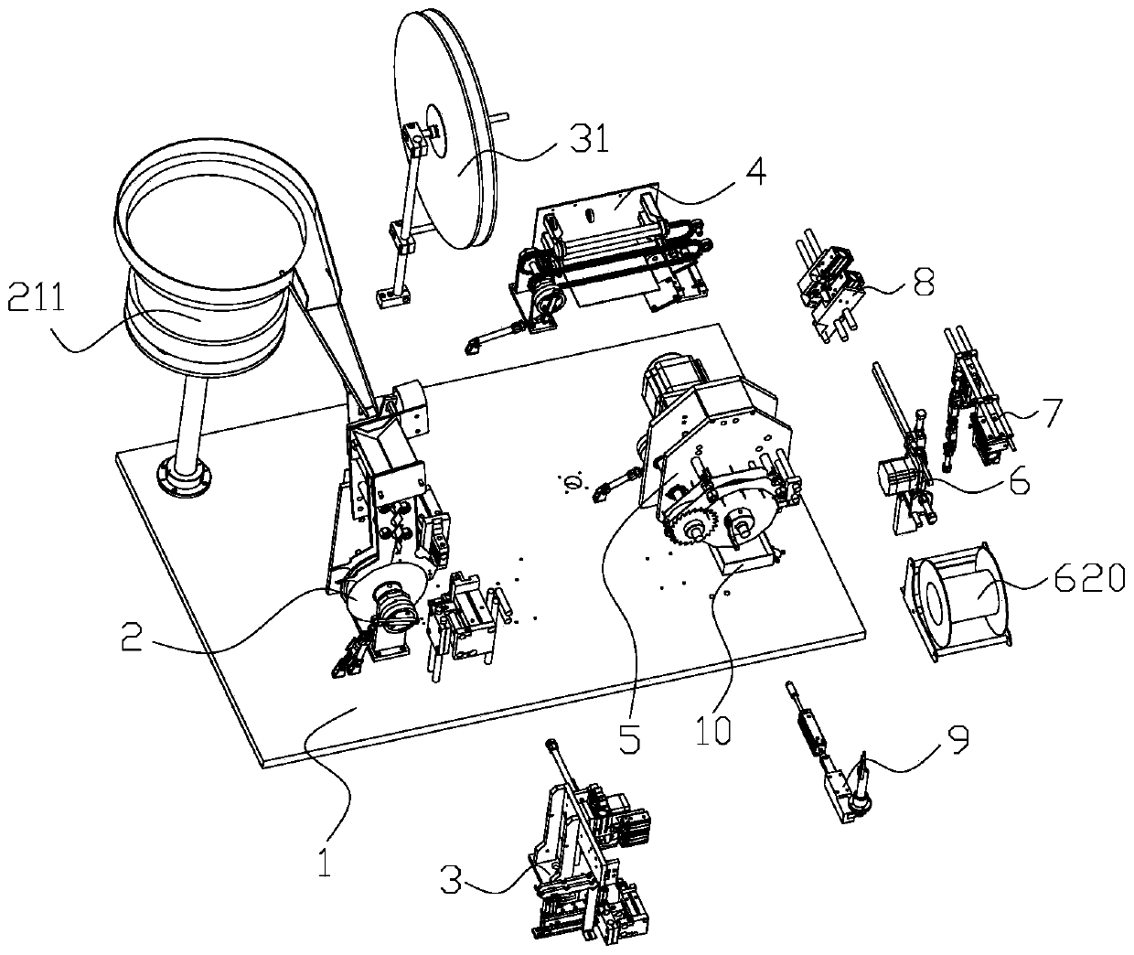
[0027] Such as fig


PUM


Abstract

The invention relates to the field of production of electronic components. Automatic resistor production equipment comprises a rack, a fuse bush assembling device, a heating device, a Teflon feed assembling device, a slicer device and a pin bending device. The fuse bush assembling device is used for arranging a bush on a fuse in a sleeving manner; the heating device is sued for heating the bush fuse and conveying the bush fuse to the Teflon feed assembling device; a conveying module is used for conveying and discharging; a Teflon feeding module is arranged on the rack for conveying and feedingTeflon; a pipe pushing module is used for pushing Teflon; the slicer device is used for cutting off and correcting; and the pin bending device is used for bending and forming the fuse of the bush fuse discharged by the conveying module, and a discharging collecting box is arranged below the discharge end of the conveying module on the rack. The automatic resistor production equipment has the technical effects that manual operations are replaced; full-automatic production of resistors is achieved by means of the equipment; and a series of processing operations such as assembling, conveying, heating, cutting off and trimming and pin bending are completed.

Description


Claims


Application Information

Patent Timeline
Owner 楼显华
Why Eureka
Try Eureka