Optical imaging lens
An optical imaging lens and lens technology, applied in optics, optical components, instruments, etc., can solve the problems of limited installation space of the front camera, and achieve the effect of small head size, high image quality, and good workmanship
- Summary
- Abstract
- Description
- Claims
- Application Information
AI Technical Summary
Problems solved by technology
Method used
Image

Examples
Example Embodiment
[0056] Example 1
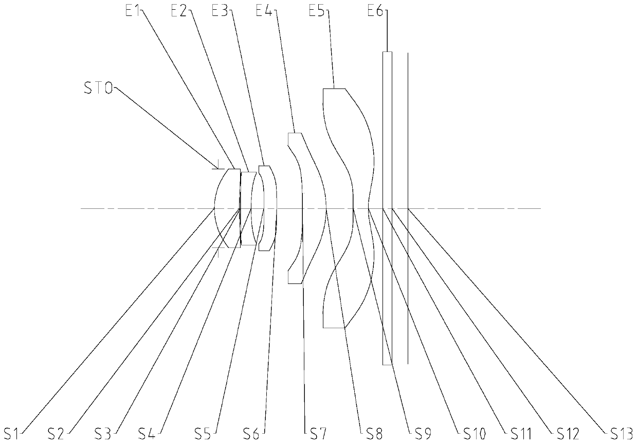
[0057] The following reference Figure 2 to Figure 3D The optical imaging lens according to Embodiment 1 of the present application is described. figure 2 A schematic structural diagram of an optical imaging lens according to Embodiment 1 of the present application is shown.
[0058] Such as figure 2 As shown, the optical imaging lens includes in order from the object side to the image side along the optical axis: a stop STO, a first lens E1, a second lens E2, a third lens E3, a fourth lens E4, a fifth lens E5 and a filter Piece E6.
[0059] The first lens E1 has a positive refractive power, the object side surface S1 is a convex surface, and the image side surface S2 is a concave surface. The second lens E2 has negative refractive power, the object side surface S3 is a convex surface, and the image side surface S4 is a concave surface. The third lens E3 has a positive refractive power, the object side surface S5 is a convex surface, and the image side surface S6
Example Embodiment
[0071] Example 2
[0072] The following reference Figure 4 to Figure 5D The optical imaging lens according to Embodiment 2 of the present application is described. In this embodiment and the following embodiments, for the sake of brevity, some descriptions similar to Embodiment 1 will be omitted. Figure 4 A schematic structural diagram of an optical imaging lens according to Embodiment 2 of the present application is shown.
[0073] Such as Figure 4 As shown, the optical imaging lens includes in order from the object side to the image side along the optical axis: a stop STO, a first lens E1, a second lens E2, a third lens E3, a fourth lens E4, a fifth lens E5 and a filter Piece E6.
[0074] The first lens E1 has a positive refractive power, the object side surface S1 is a convex surface, and the image side surface S2 is a concave surface. The second lens E2 has negative refractive power, the object side surface S3 is a convex surface, and the image side surface S4 is a concave sur
Example Embodiment
[0083] Example 3
[0084] The following reference Figure 6 to Figure 7D The optical imaging lens according to Embodiment 3 of the present application is described. Image 6 A schematic structural diagram of an optical imaging lens according to Embodiment 3 of the present application is shown.
[0085] Such as Image 6 As shown, the optical imaging lens includes in order from the object side to the image side along the optical axis: a stop STO, a first lens E1, a second lens E2, a third lens E3, a fourth lens E4, a fifth lens E5 and a filter Piece E6.
[0086] The first lens E1 has a positive refractive power, the object side surface S1 is a convex surface, and the image side surface S2 is a concave surface. The second lens E2 has negative refractive power, the object side surface S3 is a convex surface, and the image side surface S4 is a concave surface. The third lens E3 has a positive refractive power, the object side surface S5 is a concave surface, and the image side surface S6
PUM
| Property | Measurement | Unit |
|---|---|---|
| Maximum viewing angle | aaaaa | aaaaa |
Abstract
Description
Claims
Application Information
 - R&D Engineer
- R&D Manager
- IP Professional
- Industry Leading Data Capabilities
- Powerful AI technology
- Patent DNA Extraction
Browse by: Latest US Patents, China's latest patents, Technical Efficacy Thesaurus, Application Domain, Technology Topic.
© 2024 PatSnap. All rights reserved.Legal|Privacy policy|Modern Slavery Act Transparency Statement|Sitemap