Machining center electric spindle and machining center

A machining center and electric spindle technology, applied in metal processing equipment, metal processing machinery parts, manufacturing tools, etc., can solve the problems of long overhang of the front bearing and weak rigidity of the spindle, and achieve wide application range, prolong service life, The effect of increasing hardness

Inactive Publication Date: 2019-12-24
GREE ELECTRIC APPLIANCES INC
View PDF7 Cites 1 Cited by
  • Summary
  • Abstract
  • Description
  • Claims
  • Application Information

AI Technical Summary

Benefits of technology

This patented design allows for better flexibility when converting from one mode (turning) into another without losing its strength or durability over time due to increased stiffness caused by an improved structure on top of it's rotating hub.

Problems solved by technology

This patented technical problem addressed by this patents relates to improving the strength of cutting tools with integrated turning/milling capabilities without compromising their functionality or performance.

Method used


Image

  • Machining center electric spindle and machining center

Examples


Embodiment Construction

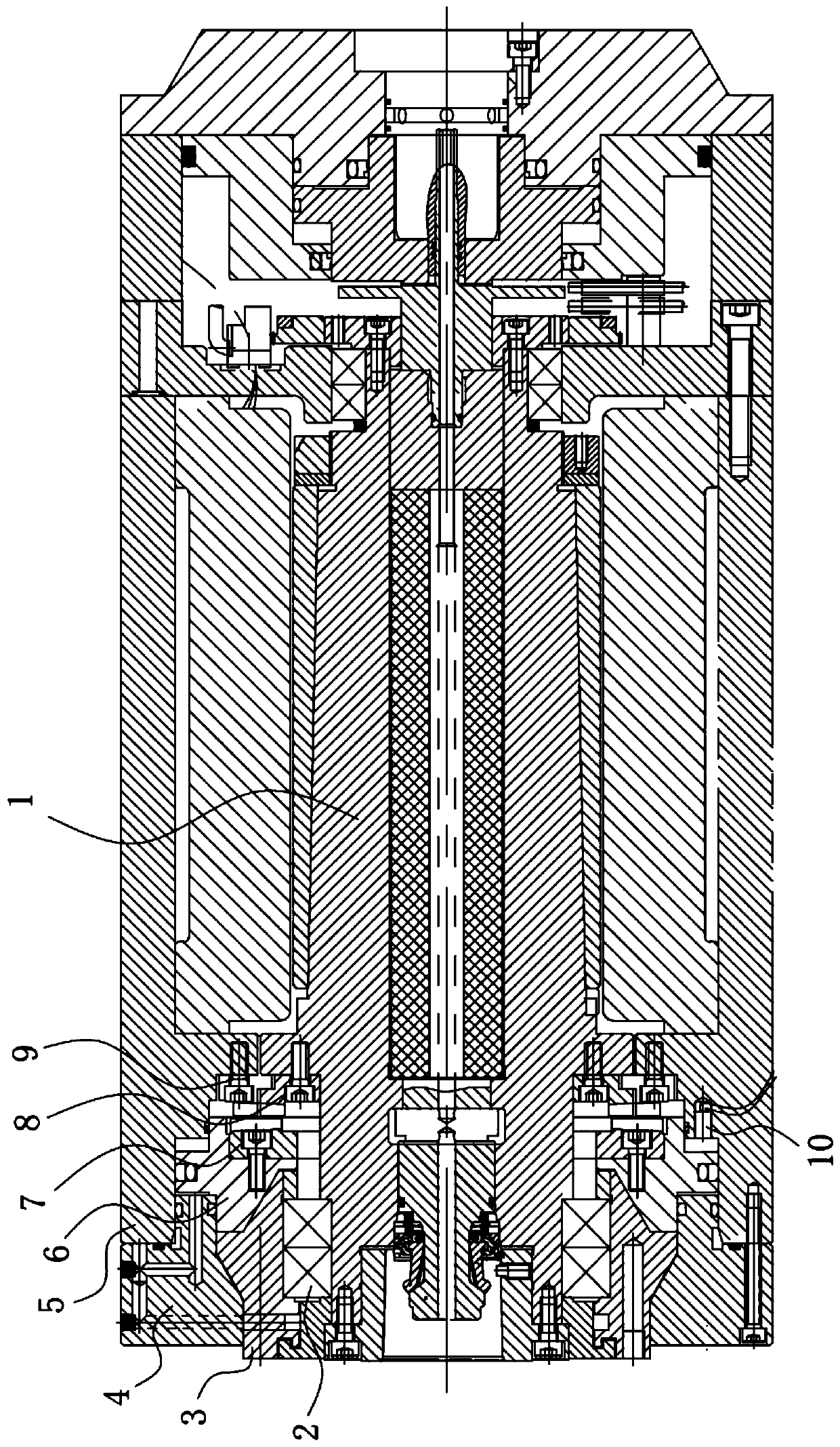
[0023] The technical solutions of the present invention will be further described below in conjunction with the accompanying drawings and through specific implementation methods.

[0024] The embodiment discloses an electric spindle of a machining center and a machining center including the electric spindle, so that the machining center has turning and milling conversion functions. Such as figure 1 As shown, the electric spindle of the machining center includes a shaft core 1, and a front bearing group 2 is sleeved on the outside of the shaft core 1, and a turning and milling conversion mechanism is arranged on the outside of the shaft core 1 and at the rear end of the front bearing group 2. The milling conversion mechanism is configured such that the shaft core 1 can rotate in the front bearing group 2 when the milling process or the drilling process needs to be performed, and the shaft core 1 is fixed relative to the front bearing group 2 when the turning process needs to be pe


PUM


Abstract

The invention discloses a machining center electric spindle and a machining center and belongs to the technical field of machining equipment. The machining center electric spindle and the machining center are designed for solving the problem of low rigidity of an existing spindle. The machining center electric spindle comprises a spindle core. The outer side of the spindle core is sleeved with a front bearing set. A turning and milling switching mechanism is arranged in the position, located at the rear end of the front bearing set, of the outer side of the spindle core and is configured in the mode that when a milling process or a drilling process needs to be conducted, the spindle core can rotate in the front bearing set. When a turning process needs to be conducted, the spindle core isfixed relative to the front bearing set. Compared with an existing machining center spindle core, the machining center electric spindle and the machining center are higher in overall rigidity, the service life of the spindle core is prolonged under the circumstance that turning and milling can be switched smoothly, hardness of allowably turned workpieces is improved, and the application range is wider.

Description


Claims


Application Information

Patent Timeline
Owner GREE ELECTRIC APPLIANCES INC
Why Eureka
Try Eureka