Air conduit for automobile refueling pipe and manufacture method thereof

An air duct and refueling pipe technology, which is applied to vehicle components, layout combined with internal combustion engine fuel supply, power plant and other directions, can solve the problems of narrow pipeline installation space, design of refueling pipe, troublesome manufacturing, etc., and achieves low manufacturing cost, The effect of simple processing and convenient connection

Pending Publication Date: 2020-02-11
NINGBO SHUNJIANG AUTO PARTS MFG
View PDF0 Cites 0 Cited by
  • Summary
  • Abstract
  • Description
  • Claims
  • Application Information

AI Technical Summary

Benefits of technology

This patented technology describes how it works well when adding or removing liquid fuels into cars without causing damage caused by excessive vapor pressure inside them. A special type called a fuel tube has two parts: one part attached to the other's end while another section extends through its middle. There may be multiple pipes made up of different materials like metal tubings, plastic material, rubber, etc., joined together along their entire length. These connections allow gases produced during refuelling to escape safely outdoors where they could harm people nearby on board. Additionally, this system allows for easy connection of various components such as filters and valves within the vehicle itself. Overall, these technical features improve safety standards and reduce costs associated with refueled vehicles.

Problems solved by technology

Technological Problem: Current Gasoline Vehicle Filler Pipes used on vehicles require manual adjustment during initial assembly due to limited mountings within their internal passages. Additionally, they may cause issues such as excessive pressure when trying to connect them properly without causing damage.

Method used


Image

  • Air conduit for automobile refueling pipe and manufacture method thereof
  • Air conduit for automobile refueling pipe and manufacture method thereof
  • Air conduit for automobile refueling pipe and manufacture method thereof

Examples


Embodiment Construction

[0029] The present invention will be further described in detail below in conjunction with the accompanying drawings and embodiments.

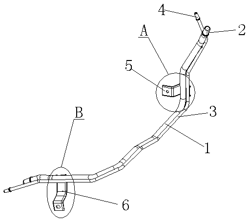
[0030] like Figure 1 to Figure 5 Shown is the structural representation of the present invention,

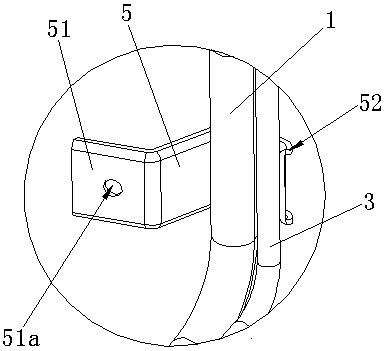
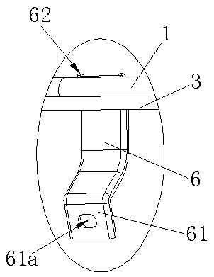
[0031] The reference signs therein are: carbon tank ventilation steel pipe 1, first shrinkage 2, first limit ring 21, first retraction arc 22, ventilation steel pipe 3, second shrinkage 4, second limit ring 41 , the second retracted arc 42, the first fixed bracket 5, the first fixed plane 51, the first fixed hole 51a, the first reinforced edge 52, the second fixed bracket 6, the second fixed plane 61, the second fixed hole 61a , the second reinforced edge 62 .

[0032] like Figure 1 to Figure 5 as shown,

[0033] An air duct for an automobile fuel pipe, comprising a carbon canister breather steel pipe 1 for connecting the fuel filler pipe and a carbon canister, the carbon canister breather steel pipe 1 is a continuous integral structure, and


PUM

PropertyMeasurementUnit
Lengthaaaaaaaaaa
Lengthaaaaaaaaaa

Abstract

The invention discloses an air conduit for an automobile refueling pipe. The air conduit for the automobile refueling pipe comprises a carbon tank aeration steel pipe for connecting the refueling pipewith a carbon tank, wherein the carbon tank aeration steel pipe is of a continuous integrated structure, first shrinkage openings are manufactured in two ends of the carbon tank aeration steel pipe,first limiting rings are formed at the roots of the first shrinkage openings, first concave arcs are manufactured in the heads of the first shrinkage openings, an aeration steel pipe used for connecting an oil tank with an ash filter is arranged beside the carbon tank aeration steel pipe and along the trend of the carbon tank aeration steel pipe, second shrinkage openings are manufactured in two ends of the aeration steel pipe, second limiting rings are formed at the roots of the second shrinkage openings, second concave arcs are manufactured in the heads of the second shrinkage openings, anda first fixed support and a second fixed support are fixed on the carbon tank aeration steel pipe and the aeration steel pipe in a welding mode. A manufacture method of the air conduit for the automobile refueling pipe includes the steps: first manufacturing the carbon tank aeration steel pipe and the aeration steel pipe, welding the first fixed support and the second fixed support after placing the carbon tank aeration steel pipe and the aeration steel pipe in a parallel mode, performing washing and spraying after completing gas tightness inspection, and then warehousing the air conduit. Theair conduit for the automobile refueling pipe is simple in processing method and low in manufacture cost.

Description


Claims


Application Information

Patent Timeline
Owner NINGBO SHUNJIANG AUTO PARTS MFG
Why Eureka
Try Eureka