Wind field gradient measuring method

A measurement method and wind field technology, applied in the direction of fluid velocity measurement, velocity/acceleration/impact measurement, measurement device, etc., can solve the action requirements of unmanned aerial vehicles, high accuracy requirements, can not achieve three-dimensional space wind field measurement, Circuit safety, reliability reduction and other issues, to achieve the effect of reducing equipment investment, low cost, simple and lightweight installation

Inactive Publication Date: 2020-04-07
XIAMEN UNIV
View PDF9 Cites 2 Cited by
  • Summary
  • Abstract
  • Description
  • Claims
  • Application Information

AI Technical Summary

Benefits of technology

The technical effects described in this patented inventions include improved efficiency during flight operations without requiring excessive effort from pilots while maintaining precise measurements over altitudes. Additionally, there may exist various ways to estimate ground level gradients based solely upon gravity alone instead of just relying exclusively on aerodynamic forces like lift coefficients (F) measured separately. Overall, these improvements improve safety, performance, and affordance compared to current techniques such as laser radar systems.

Problems solved by technology

Technologies described include techniques like sensors on heliostats called "iron radars," optically scanning through water waves caused by turbulence, allowing measurements over short distances without being affected by factors other nearby. However these technics have limitations due to their slow response times and require expensive equipment. Additionally, there may exist situations where they could fail if needed again because they were designed based solely upon current conditions rather than accurately predict future changes during operation.

Method used


Image

  • Wind field gradient measuring method
  • Wind field gradient measuring method
  • Wind field gradient measuring method

Examples


Embodiment Construction

[0050] The present invention will be described in detail below in conjunction with the accompanying drawings and specific embodiments.

[0051] Such as Figure 1 to Figure 6 as shown,

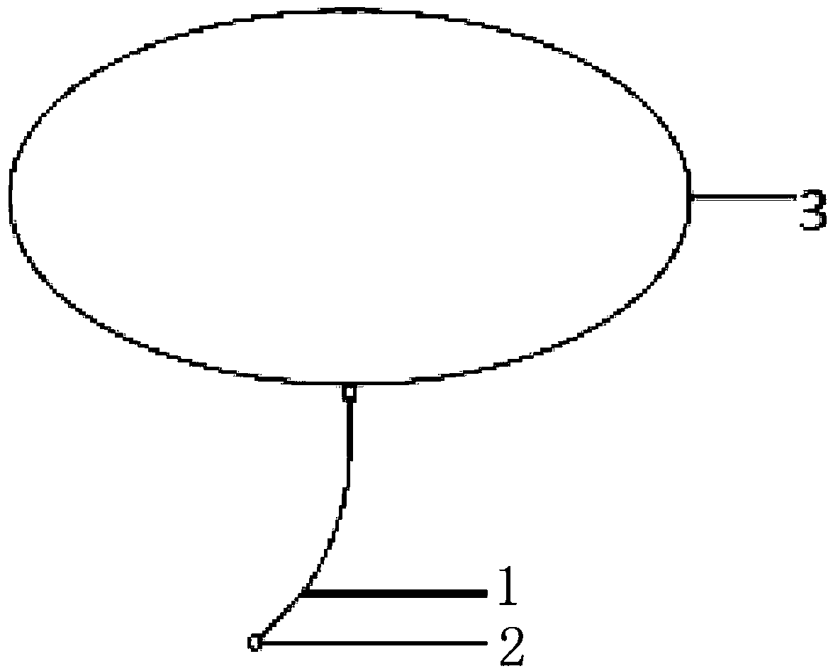
[0052] Whole instrument device is arranged on aerostat 3 such as airship, and the hanging rope 1 of a long about 100 meters of hanging ball at the lower end hangs a hanging ball 2 at the end of hanging rope 1.

[0053] The specific steps for measuring the wind speed by using the hanging rope 1 and the hanging ball 2 are as follows:

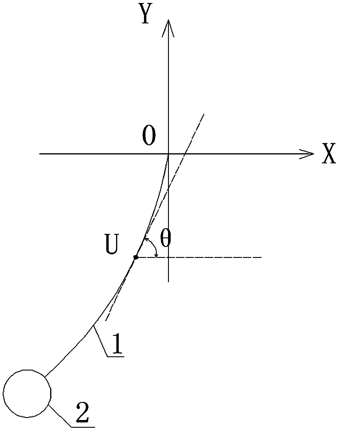
[0054] Step 1: The hanging ball 2 is displaced by the load of the wind field, and at the same time drives the suspension rope 1 to move, and detects the deflection angle of the U point on the suspension rope 1 or the pulling force on the suspension rope 1 through the detector fixed at the lower end of the aerostat 3; There are many ways to measure the deflection angle of the end of the suspension rope 1 involved. The deflection angle of the suspension rope 1 can be


PUM


Abstract

The invention relates to a wind field gradient measuring method. A lifting rope is suspended at the lower end of an aerostat, and a hanging ball is suspended at the tail end of the lifting rope. The change of the lifting rope along with time is not considered, and the measuring method comprises the following steps: 1, the hanging ball moving under a wind field load; meanwhile, the lifting rope being driven to move, taking any point U on the lifting rope; establishing a rectangular plane coordinate system by taking the fixed end point of the lifting rope as an original point 0, the initial balance position of the lifting rope as a Y axis, the vertical upward direction as a positive direction, the direction vertical to the Y axis as an X axis and the horizontal rightward direction as a positive direction, and detecting an included angle theta between the lifting rope at a U point and an OX axis or a tensile force T1 borne by the lifting rope at the U point. The method does not need a large amount of electric energy consumption, replaces a traditional wind speed detection instrument with a model calculation mode, is high in precision and reliability, can effectively measure the gradient of the high-altitude wind field in a low-energy-consumption, long-term and high-precision mode, and can be used for controlling the airship to stay at a low-wind-speed height and reducing energy consumption.

Description


Claims


Application Information

Patent Timeline
Owner XIAMEN UNIV
Why Eureka
Try Eureka