Girdling and stripping device for outer insulating sheath of cable

A technology of external insulation and cables, which is applied in the direction of cable installation devices, cable installation, dismantling/armored cable equipment, etc., can solve the problems of difficult operation, inconvenient operation, affecting operation, etc., and achieve the effect of high degree of automation

Active Publication Date: 2020-04-10
XINYI XIYI ADVANCED MATERIALS RES INST OF IND TECH CO LTD
View PDF7 Cites 10 Cited by
  • Summary
  • Abstract
  • Description
  • Claims
  • Application Information

AI Technical Summary

Benefits of technology

This technology allows for efficient transmission or processing of cables without damaging them during their production process. By driving it along curved paths while being driven around multiple wheel systems, this system ensures accurate movement over different directions. Additionally, there're also automatic detection methods used to detect any damage caused when removing an outer layer (insulating material) before delivering the final product. Overall, these technical improvements improve efficiency and quality of producing electrical wires.

Problems solved by technology

The technical problem addressed by this patented technology relating to improving the efficiency and accuracy with removing thin layers from electrical wires during maintenance or replacement operations has been solved through an improved method called automated wire stripper (ACS).

Method used


Image

  • Girdling and stripping device for outer insulating sheath of cable
  • Girdling and stripping device for outer insulating sheath of cable
  • Girdling and stripping device for outer insulating sheath of cable

Examples


Embodiment Construction

[0016] Combine below Figure 1-5 The present invention is described in detail, and for convenience of description, the orientations mentioned below are now stipulated as follows: figure 1 The up, down, left, right, front and back directions of the projection relationship itself are the same.

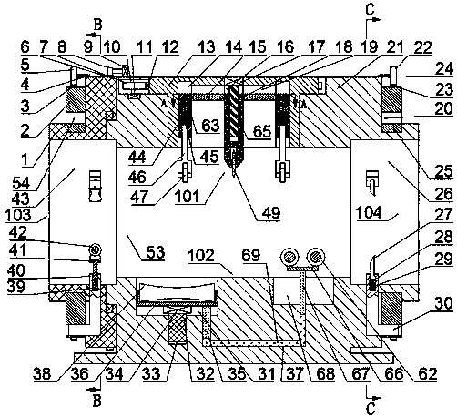
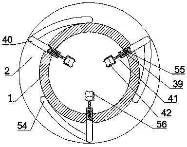
[0017] refer to Figure 1-5 , according to an embodiment of the present invention, a device for cutting and stripping the outer insulation of cables, including a main body 21, a cutting cavity 53 penetrating left and right is arranged in the main body 21, and a cutting cavity 53 is provided on the left side of the cutting cavity 53. Clamping delivery mechanism 103, said clamping delivery mechanism 103 includes clamping delivery body 1, said clamping delivery body 1 is provided with left and right through and communicated with said cutting cavity 53 rotating delivery cavity 43, said rotary delivery Three L-shaped delivery arms 40 are evenly slidably connected between the inner wall of the


PUM


Abstract

The invention discloses a girdling and stripping device for an outer insulating sheath of a cable. The device comprises a main machine body. A left-right through cutting cavity is formed in the main machine body. A clamping delivery mechanism is arranged on the left side of the cutting cavity. A rotary delivery cavity which is through left and right and communicates with the cutting cavity is formed in the clamping delivery mechanism. Three L-shaped delivery machine arms are uniformly arranged on the inner wall of the rotary delivery cavity. According to the invention, through rotation and delivery of the delivery arm, a cable is fed into the cutting cavity, annular and linear cutting is conducted on the surface of the cable through the cutting knife, the insulation sheath of the cable iscut off, and accurate and reliable cutting is guaranteed through supporting of the supporting mechanism. Meanwhile, the cut insulation sheath is automatically separated through the peeling mechanism,and the cable and cutting waste are conveyed out respectively.

Description


Claims


Application Information

Patent Timeline
Owner XINYI XIYI ADVANCED MATERIALS RES INST OF IND TECH CO LTD
Why Eureka
Try Eureka