Welded joint creep deformation prediction method based on DIC technology

A technology of welded joints and creep deformation, applied in the direction of applying stable tension/pressure to test the strength of materials, measuring devices, and preparation of test samples, which can solve the problems of lack of extraction of creep deformation data, etc., to solve the problem of creep deformation Deformation characterization problem, effect of reducing measurement noise

Active Publication Date: 2020-04-21
HEFEI GENERAL MACHINERY RES INST +1
View PDF6 Cites 2 Cited by
  • Summary
  • Abstract
  • Description
  • Claims
  • Application Information

AI Technical Summary

Benefits of technology

This patented technique allows us to accurately determine how well two materials have been joined together during manufacturing processes without causing damage or affect their performance. By measuring changes over time that occur when they're being connected with other parts, we aim to identify issues such as stress concentration zones (SZ) within these connections. Additionally, this analysis helps predict future cracks formed due to thermal cycling fatigue.

Problems solved by technology

The technical problem addressed in this patents relates to correctly estimating how well an alloy or steel component can withstand extreme temperatures without losing its effectiveness over time when subjected to stress caused by external factors like vibrations. This requires precise analysis of these stresses on specific parts of the system's construction. Current methods have limitations in representing the entire range of strain experienced at any given location within the body.

Method used


Image

  • Welded joint creep deformation prediction method based on DIC technology
  • Welded joint creep deformation prediction method based on DIC technology
  • Welded joint creep deformation prediction method based on DIC technology

Examples


Embodiment Construction

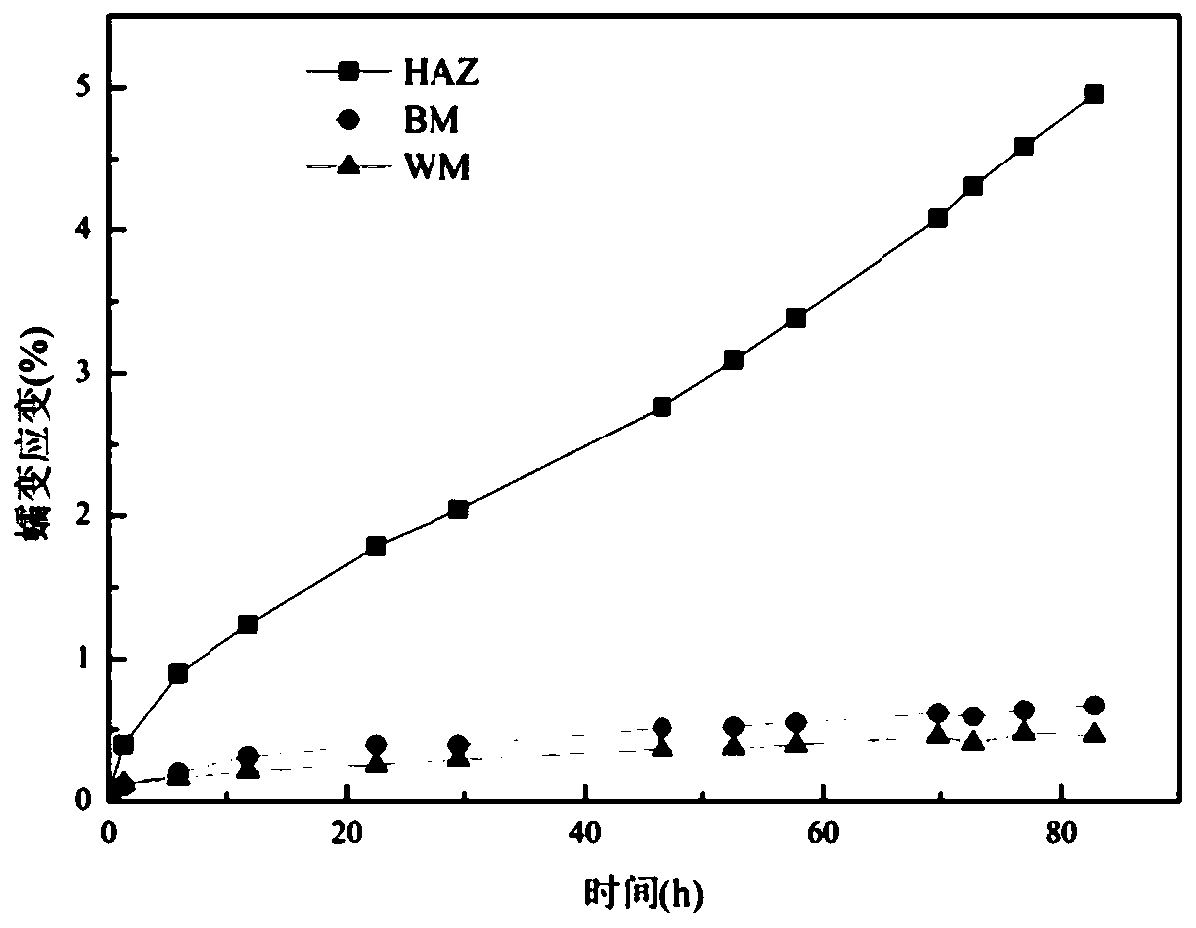
[0022] A method for predicting creep deformation of welded joints based on DIC technology, comprising the following steps:

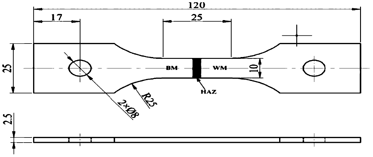
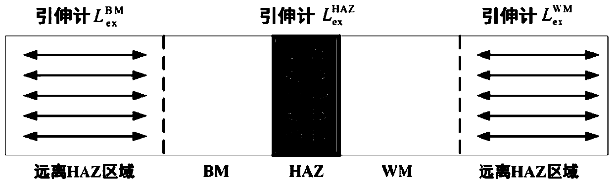
[0023] S1. Process the welded joint sample; specifically, first spray a layer of white high-temperature paint on the sample as a primer, and then spray diffuse and randomly distributed black high-temperature paint on the primer. In order to ensure the stability of the prepared high-temperature speckle, the sample was baked in a muffle furnace at a temperature of 230°C for 30 minutes. It should be noted that it is necessary to ensure that the welding heat-affected zone is located in the center of the sample, and the weld and base metal are located on both sides of the welding heat-affected zone.

[0024] In this embodiment, the sample material of the welded joint is low-alloy ferritic steel 2.25Cr1Mo0.25V, the length and width of the gauge section are 25mm and 10mm respectively, and the thickness of the sample is 2.5mm. The schematic diagram of the sample g


PUM


Abstract

The invention discloses a welded joint creep deformation prediction method based on DIC technology. The method comprises the following steps of S1, processing a welded joint sample; s2, applying a constant loading stress level to the sample, and measuring axial strain field data of the sample at a plurality of discrete moments by using the DIC technology; s3, extracting creep axial strain values of a base material, a weld joint and a welding heat affected zone; s4, changing the loading stress level of the creep test, and repeating the steps S2-S3 to obtain a creep axial strain data pair; s5, constructing a material creep constitutive model, fitting the obtained creep axial strain data pair into the creep constitutive model, and respectively obtaining optimal estimations for creep constitutive model parameters of the base material, the weld joint and the welding heat affected zone; and S6, substituting the creep constitutive model parameters into the creep constitutive model, and predicting creep deformation of the base material, the weld joint and the welding heat affected zone of the welded joint under different stress levels. The method realizes simultaneous characterization andprediction of creep deformation of different areas of a real welding joint.

Description


Claims


Application Information

Patent Timeline
Owner HEFEI GENERAL MACHINERY RES INST
Why Eureka
Try Eureka