Locking mechanism, cab rear suspension locking mechanism and vehicle

A locking mechanism and cab technology, applied in vehicle parts, superstructure, transportation and packaging, etc., can solve the problems of hydraulic lock oil pipe joint breakage, complicated unlocking operation process, hydraulic lock unlocking stuck, etc. The effect of improving safety and reducing failure rate

Active Publication Date: 2020-05-05
BEIQI FOTON MOTOR CO LTD
View PDF5 Cites 0 Cited by
  • Summary
  • Abstract
  • Description
  • Claims
  • Application Information

AI Technical Summary

Problems solved by technology

There are mainly two types of locking mechanisms related to the rear suspension of the cab. One is mechanical locking, which has a complex structure and a complicated unlocking operation process; the other is hydraulic locking. The suspension is matched with a hydraulic lock, and the inside of the hydraulic lock is equipped with an oil cylinder. The lock hook of the hydraulic lock hooks the lock pin to realize locking, and the oil cylinder drives the lock hook to move to realize unlocking.
However, when the cab and the chassis move relative to each other during driving, such as tilting, leaning forward or backward, the hydraulic lock and the lock pin will move relative to each other. The hardness of the lock shell is small, and the hydraulic lock will be unlocked due to wear and tear of the lock shell. Stuck, hydraulic lock oil pipe joints are also prone to breakage and other failures

Method used


Image

  • Locking mechanism, cab rear suspension locking mechanism and vehicle
  • Locking mechanism, cab rear suspension locking mechanism and vehicle
  • Locking mechanism, cab rear suspension locking mechanism and vehicle

Examples


Embodiment Construction

[0038] Specific embodiments of the present disclosure will be described in detail below in conjunction with the accompanying drawings. It should be understood that the specific embodiments described here are only used to illustrate and explain the present disclosure, and are not intended to limit the present disclosure.

[0039] In the present disclosure, unless stated otherwise, the used orientation words such as "upper" and "lower" usually refer to the definition based on the drawings of the corresponding drawings, and "axial" usually refers to the As far as the connecting column is concerned, "inner" and "outer" refer to the axial direction of the connecting column, the end close to the connecting ear is "inner", and the end far away from the connecting ear is "outer". In addition, the term used in this disclosure The terms "first", "second", etc. are used to distinguish one element from another, and do not have order or importance. In addition, when the following descript...


PUM


Abstract

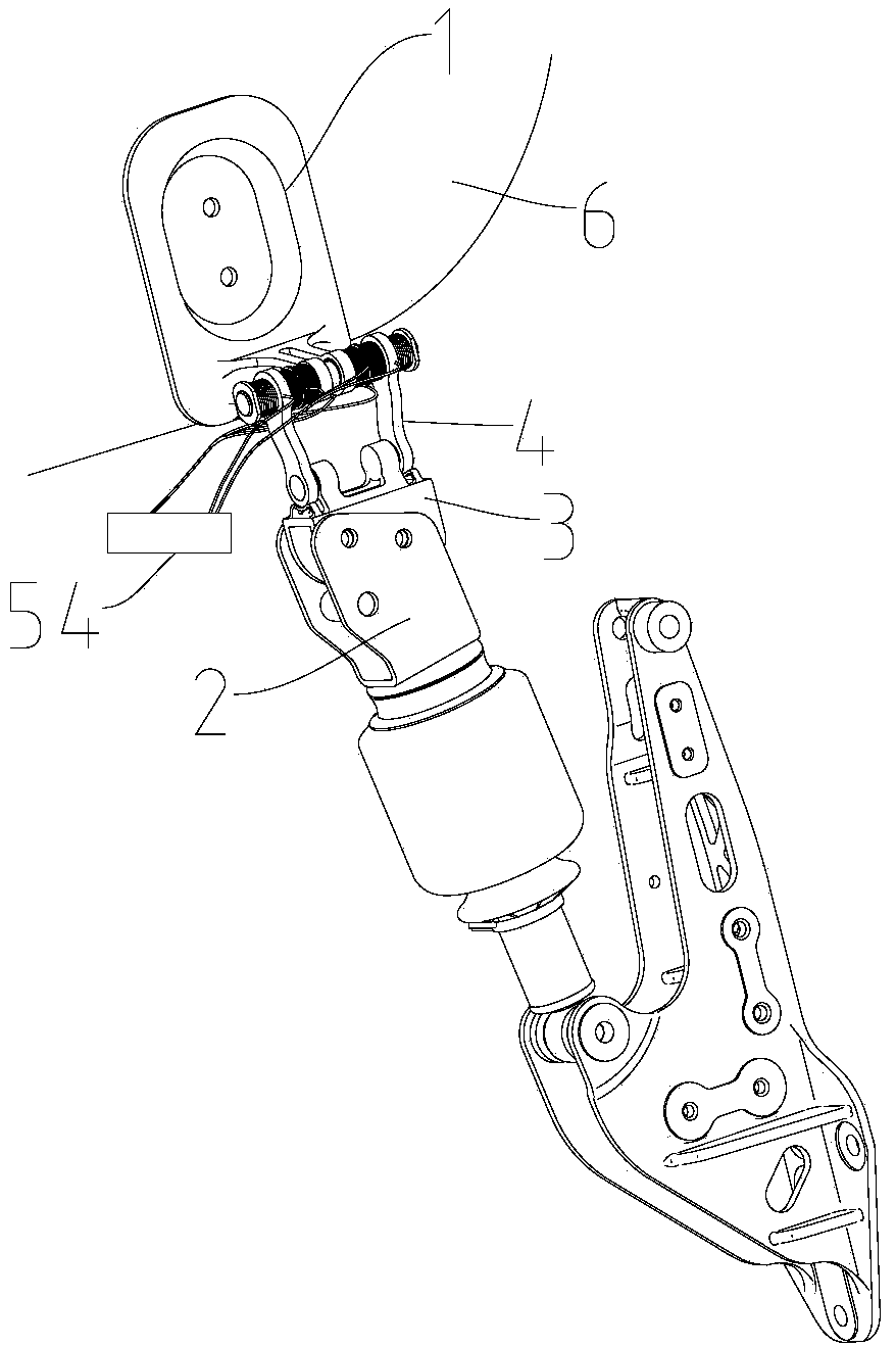
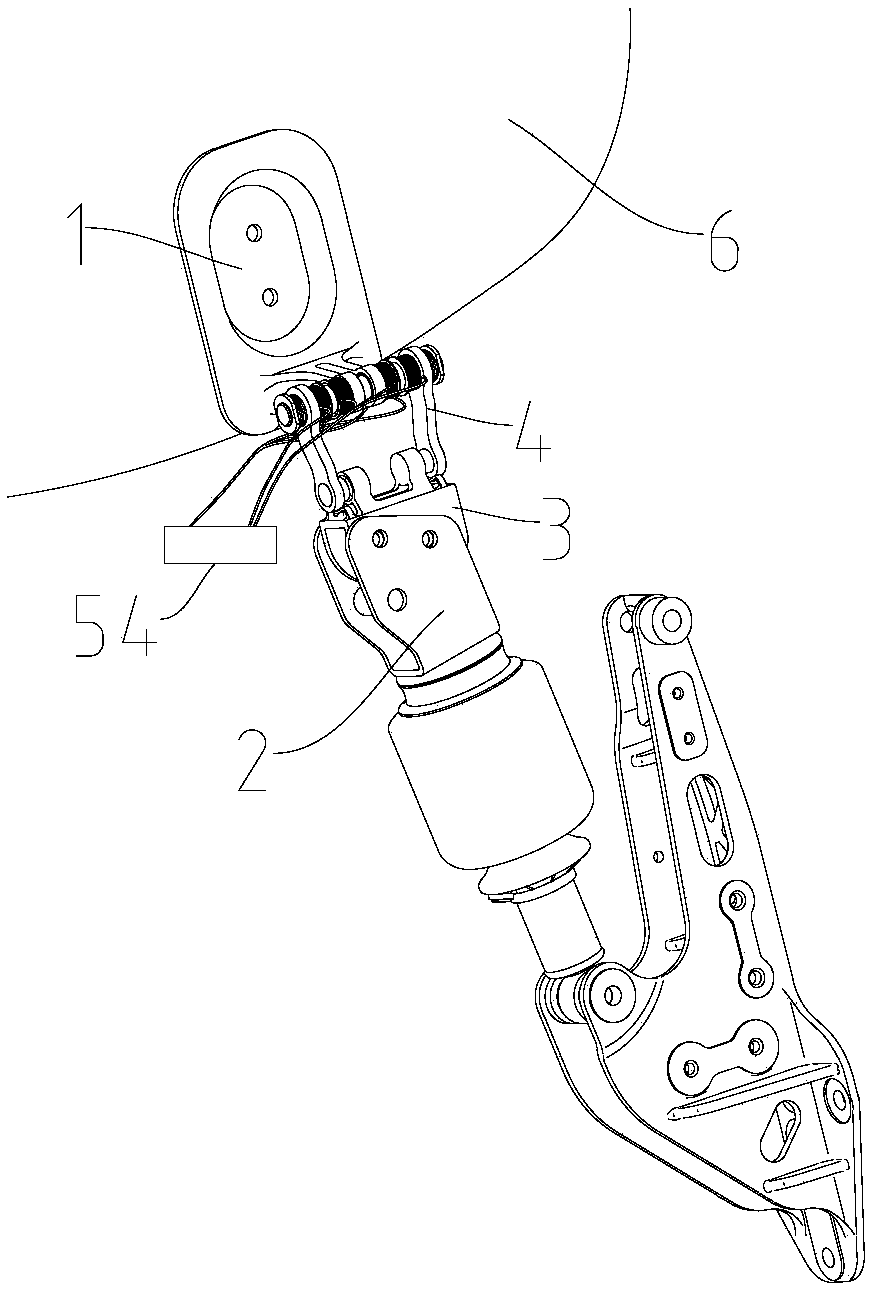
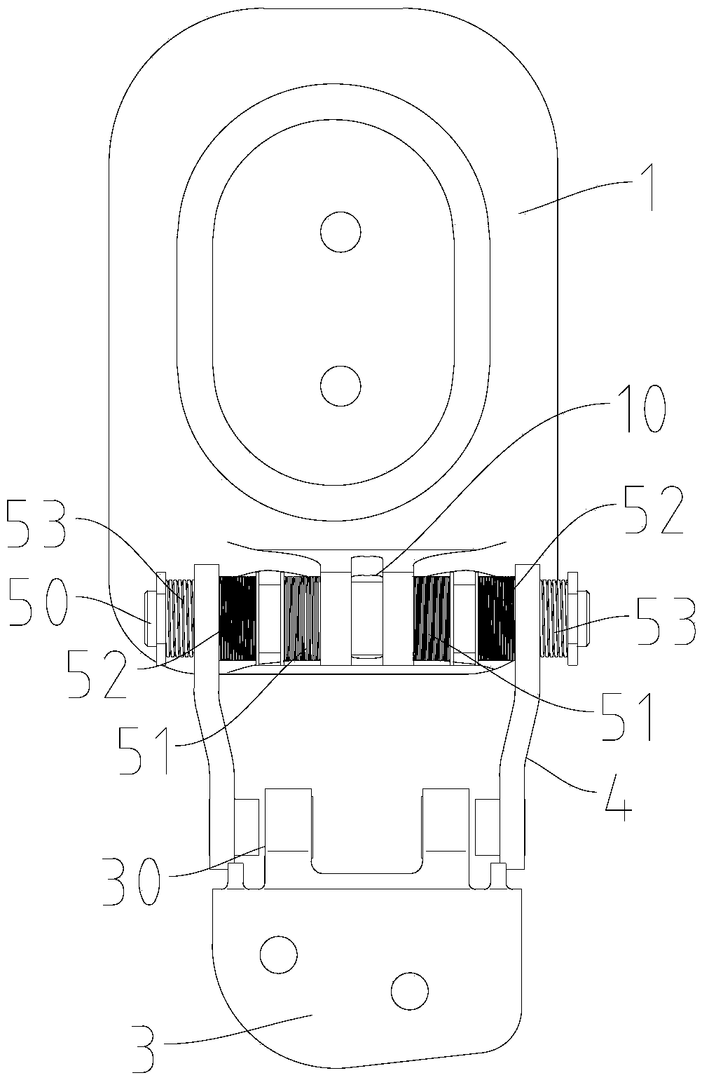
The invention relates to a locking mechanism, a cab rear suspension locking mechanism and a vehicle. The locking mechanism comprises an upper lock body, a body, a lock hook for connecting the upper lock body to the body and an electromagnetic driving assembly connected with the lock hook, wherein the locking mechanism has an unlocking state in which the electromagnetic driving assembly is poweredon and drives the lock hook to retreat from the body or a mounting hole of the upper lock body, and the upper lock body and the body are disconnected; and a locking state in which the electromagneticdriving assembly is powered off and drives the lock hook to be inserted into the mounting hole so as to connect the upper lock body with the body. The locking mechanism is advantaged in that stable connection between the upper lock body and the body can be achieved in a power-off state, connection between the upper lock body and the body can be disconnected in a power-on state, rapid switching between the locking state and the unlocking state can be achieved, operation is convenient, response is rapid, the risk of self-disconnection caused by external force interference is avoided, the failurerate of the locking mechanism is reduced, and use safety is improved.

Description

technical field [0001] The present disclosure relates to the field of suspension locking, in particular to a locking mechanism, a cab rear suspension locking mechanism and a vehicle. Background technique [0002] The locking mechanism, such as the cab rear suspension locking mechanism, is in the locked state during driving, which can ensure the stable connection between the cab and the chassis. When the cab needs to be turned over, the The locking mechanism switches to the unlocked state. There are mainly two types of locking mechanisms related to the rear suspension of the cab. One is mechanical locking, which has a complex structure and a complicated unlocking operation process; the other is hydraulic locking. The suspension is matched with a hydraulic lock, and the inside of the hydraulic lock is equipped with an oil cylinder. The lock hook of the hydraulic lock hooks the lock pin to achieve locking, and the oil cylinder drives the lock hook to move to unlock. However, ...

Claims


Application Information

Patent Timeline
IPC IPC(8): B62D33/07
CPCB62D33/071
Inventor 李静
Owner BEIQI FOTON MOTOR CO LTD
Why Eureka
Try Eureka