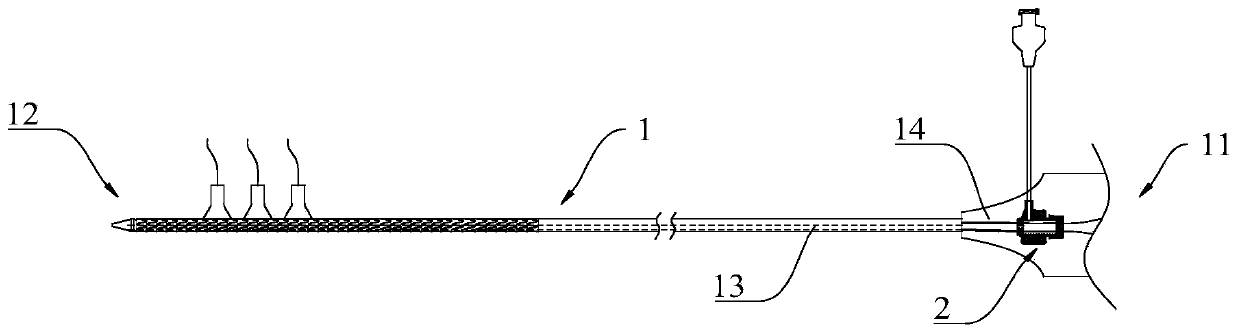
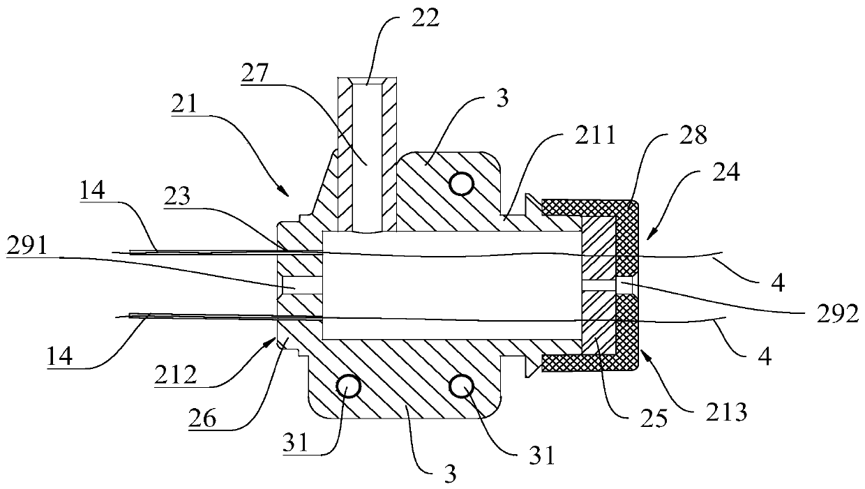
Stent implantation conveyor and implantation system
A conveyor and main body technology, applied in the medical field of implantation, can solve the problems of increasing the risk of myocardial infarction, cerebral infarction, air embolism, etc., and achieve the effect of improving the effect and reducing the injury
- Summary
- Abstract
- Description
- Claims
- Application Information
AI Technical Summary
Problems solved by technology
Method used
Image

Examples
Example Embodiment
[0021] The specific embodiments of the present disclosure will be described in detail below with reference to the accompanying drawings. It should be understood that the specific embodiments described herein are only used to illustrate and explain the present disclosure, and are not used to limit the present disclosure.
[0022] In the present disclosure, if no explanation is made to the contrary, the orientation words used such as “inner and outer” refer to the inner and outer contours of the corresponding components, and the “inner end” of the stent implantation conveyor is Refers to the end that can be implanted into the human body, and the "outer end" refers to the end outside the human body. The above-mentioned location words are only used to explain and describe the present disclosure, and are not construed as limiting the present disclosure. In addition, terms such as "first", "second", etc. are used to distinguish one element from another, and do not have sequence or import
PUM
 Abstract
Description
Claims
Application Information
 - R&D Engineer
- R&D Manager
- IP Professional
- Industry Leading Data Capabilities
- Powerful AI technology
- Patent DNA Extraction
Browse by: Latest US Patents, China's latest patents, Technical Efficacy Thesaurus, Application Domain, Technology Topic.
© 2024 PatSnap. All rights reserved.Legal|Privacy policy|Modern Slavery Act Transparency Statement|Sitemap