Method and device for controlling holder
A technology for controlling PTZ and PTZ, which is applied in the computer field and can solve problems such as affecting the execution time of other tasks and being unable to execute in time.
- Summary
- Abstract
- Description
- Claims
- Application Information
AI Technical Summary
Problems solved by technology
Method used
Image

Examples
Example Embodiment
[0051] Example 1
[0052]As mentioned above, in the prior art, the PTZ usually executes different tasks in a sequential manner. As long as a control command for the PTZ is received, it is written into a message queue and executed in sequence. For example, if the rotation instruction 1 with a delay of 5s (seconds) is received first, the instruction is written into the message queue, and then the real-time rotation instruction 2 is received, and the instruction is written into the message queue again. After waiting for 5s, execute rotation command 1, and then execute rotation command 2. But in fact, the motivation for sending the real-time rotation command 2 is to expect to execute immediately instead of waiting, so this method of controlling the gimbal in the prior art cannot meet the requirements of task execution. Based on this defect, this embodiment provides a method for controlling a pan-tilt, which can meet different control requirements in the process of controlling the pa
Example Embodiment
[0077] Example 2
[0078] Based on the same concept, Embodiment 2 of the present application provides an apparatus for controlling a pan / tilt, which can meet different control requirements in the process of controlling a pan / tilt mounted with a camera. The schematic diagram of the device is shown in Figure 7 As shown, it includes: a task writing module 202 and a task execution module 204, wherein,
[0079] The task writing module 202 can be used to:
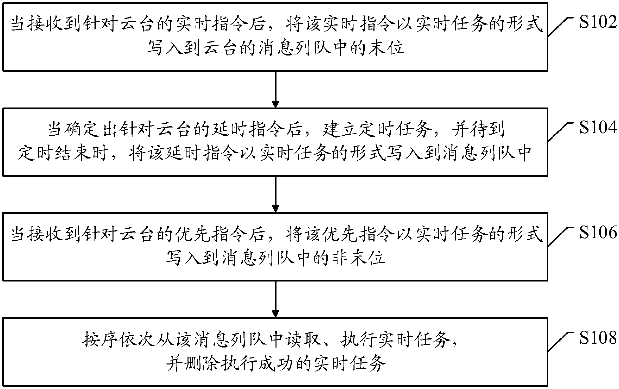
[0080] After receiving the real-time command for the gimbal, write the real-time command in the form of a real-time task to the last position in the message queue of the gimbal;
[0081] After determining the delay command for the PTZ, establish a timing task, and when the timing ends, write the delay command into the message queue in the form of a real-time task;
[0082] After receiving the priority command for the PTZ, write the priority command to the non-last position in the message queue in the form of a real-time task
PUM
 Abstract
Description
Claims
Application Information
 - R&D Engineer
- R&D Manager
- IP Professional
- Industry Leading Data Capabilities
- Powerful AI technology
- Patent DNA Extraction
Browse by: Latest US Patents, China's latest patents, Technical Efficacy Thesaurus, Application Domain, Technology Topic.
© 2024 PatSnap. All rights reserved.Legal|Privacy policy|Modern Slavery Act Transparency Statement|Sitemap