Rudder blade supporting frame and rudder blade mounting trolley

A technology for installing trolleys and supporting frames, which is applied in the directions of lifting devices, hoisting devices, ships, etc., which can solve the problems of low construction efficiency and large potential safety hazards.

Inactive Publication Date: 2020-06-16
上海外高桥造船海洋工程项目管理有限公司
View PDF6 Cites 3 Cited by
  • Summary
  • Abstract
  • Description
  • Claims
  • Application Information

AI Technical Summary

Benefits of technology

This technology has several benefits that make it useful for various applications such as improving efficiency or reducing costs associated with certain processes like manufacturing.

Problems solved by technology

This technical problem addressed in this patented text relates to how to safely install large amounts (upwards) of heavyweight components like fender planks used for steering devices during launches without causing significant safety concerns due to their high weights.

Method used


Image

  • Rudder blade supporting frame and rudder blade mounting trolley
  • Rudder blade supporting frame and rudder blade mounting trolley
  • Rudder blade supporting frame and rudder blade mounting trolley

Examples


Embodiment 1

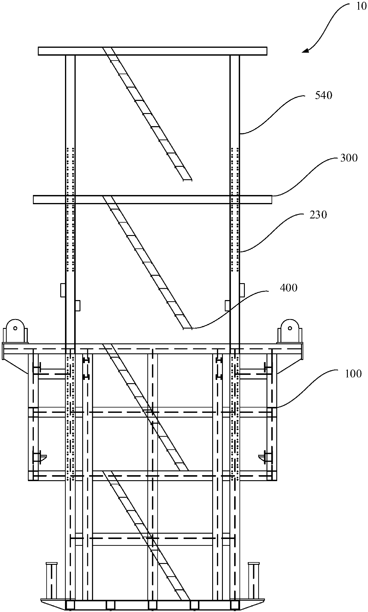
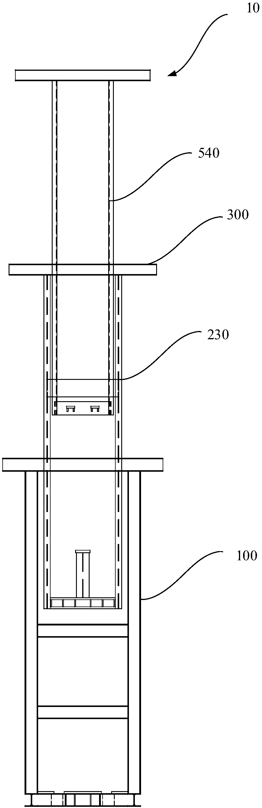
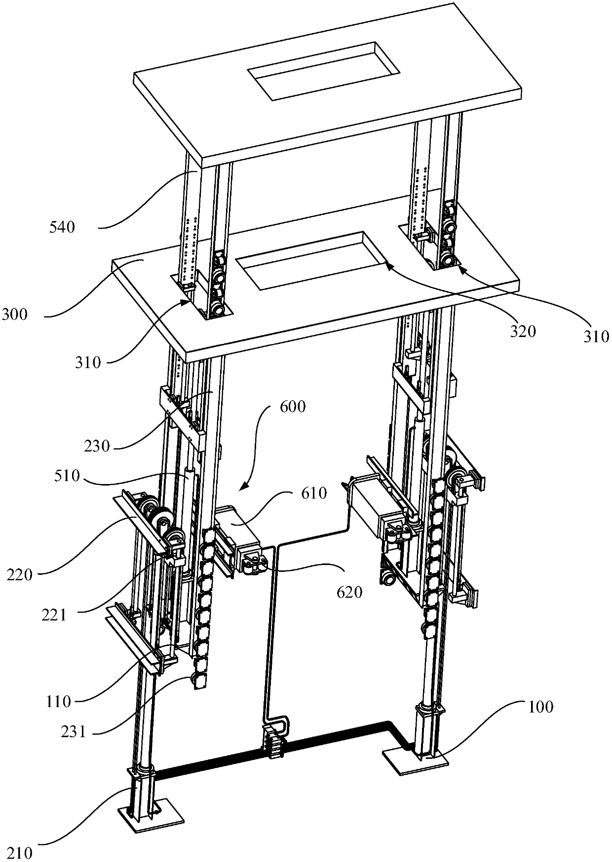
[0071] Figure 1 to Figure 4 Shown is a rudder blade support frame 10, which includes: a fixed frame 100, two first drivers 210, two groups of first pulley assemblies 220, a first moving frame 230 and a plurality of first flexible cables 240. The fixed frame 100 has a vertical channel (not shown) through which the top penetrates, and the fixed ends of the two first drivers 210 are fixed on both sides of the fixed frame 100. Two first drivers 210 are used to drive two groups of first pulley assemblies 220 to move up and down. The first mobile frame 230 is located in the vertical channel, and the first mobile frame 230 is slidably connected to the fixed frame 100. The first flexible cable 240 is wound above the pulley of the first pulley assembly 220, the two ends of the first flexible cable 240 extend vertically downward, one end of the first flexible cable 240 is fixed to the fixed frame 100, the other end of the first flexible cable 240 One end is fixed to the first moving fra

Embodiment 2

[0080] Figure 5 A rudder blade installation trolley is shown, which includes two rudder blade support frames 10 described in Embodiment 1, a main platform 20, a plurality of roller mechanisms 30 and two sliding mechanisms 40. A plurality of roller mechanisms 30 are located under the corners of the main platform 20 and drive the main platform 20 to move. Two sliding mechanisms 40 are slidably arranged on the main platform 20, and the two sliding mechanisms 40 are oppositely arranged and the sliding directions are parallel. Two rudder blade support frames 10 are respectively fixed on the two sliding mechanisms 40, and the two rudder blade support frames 10 are mirror images (not shown).

[0081] When using the rudder blade installation trolley to install the rudder blade, at first the rudder blade is placed between the two rudder blade support frames 10, by adjusting the distance between the two sliding mechanisms 40, the rising height of the rudder blade support frame 10, the ru


PUM


Abstract

The invention discloses a rudder blade supporting frame and a rudder blade mounting trolley. The rudder blade supporting frame comprises a fixing frame, two first drivers, two sets of first pulley assemblies, a first moving frame and a plurality of first flexible cables. The fixing frame is provided with a vertical channel with the top penetrating through, and the fixing ends of the two first drivers are fixed to the two sides of the fixing frame. The two first drivers are used for driving the two first pulley assemblies to move up and down. The first movable frame is located in the vertical channel and slidably connected to the fixed frame. The first flexible cable is wound above a pulley of the first pulley assembly, the two ends of the first flexible cable vertically extend downwards, one end of the first flexible cable is fixed to the fixing frame, and the other end of the first flexible cable is fixed to the first moving frame. By means of the first pulley assembly and the first flexible cable structure, the rudder blade supporting frame can adjust the height size of the rudder blade supporting frame according to the height size of a rudder blade needing to be supported. And the rudder blade mounting trolley can convey the rudder blade to a mounting position to finish mounting.

Description


Claims


Application Information

Patent Timeline
Owner 上海外高桥造船海洋工程项目管理有限公司
Why Eureka
Try Eureka