Purification device and process suitable for high-boiling-point chemical raw materials

A chemical raw material, high boiling point technology, applied in the direction of chemical instruments and methods, air heaters, fixed tubular conduit components, etc., can solve the problems of energy waste, low production efficiency, carbon deposition, etc., to improve cooling efficiency and thermal efficiency , the effect of reducing the height of the tower

Pending Publication Date: 2020-07-28
ANSHAN XINUO HEAT ENERGY TECH
View PDF0 Cites 0 Cited by
  • Summary
  • Abstract
  • Description
  • Claims
  • Application Information

AI Technical Summary

Benefits of technology

This patented design allows for efficient utilizing of excessive power from an industrial furnace's exhaust gases while also improving its performance by integrating with other systems like fuel burning equipment. It achieves this through combining these sources together into one integrated unit that provides all necessary functions needed during operation.

Problems solved by technology

This technical problem addressed in this patents relates to improving the efficient use of these highly volatile organic compounds during various industrial processes such as manufacturing fibers, resin coatings on paper products, printing plasma toner onto fabrics, etc., while also reducing wasted resources due to their difficult decomposition when exposed to air without being burnt out over an extended period of hours.

Method used


Image

  • Purification device and process suitable for high-boiling-point chemical raw materials
  • Purification device and process suitable for high-boiling-point chemical raw materials
  • Purification device and process suitable for high-boiling-point chemical raw materials

Examples


Embodiment 1

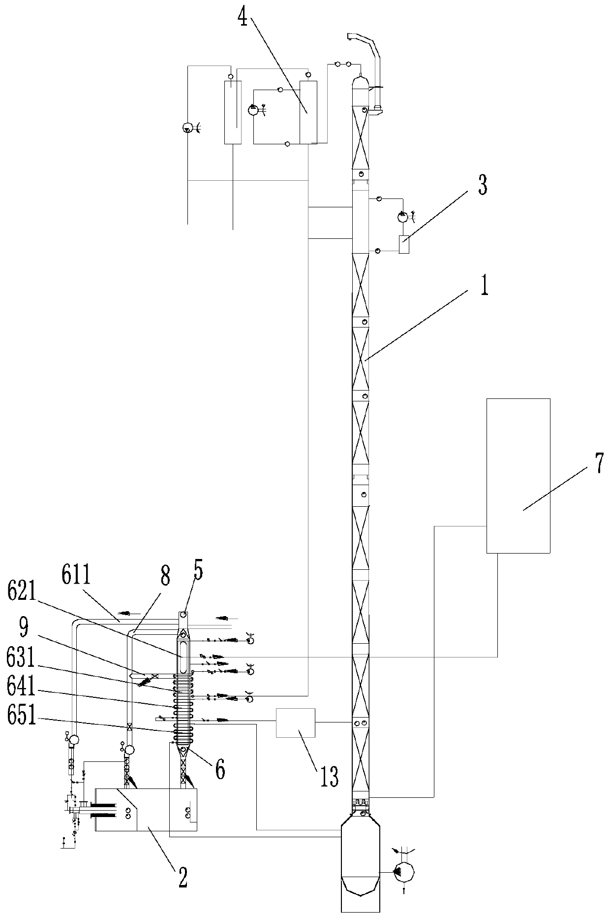
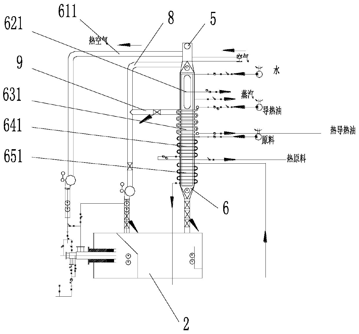
[0021] Such as Figure 1-Figure 2 , a purification device suitable for high-boiling point chemical raw materials, including a purification tower 1, a hot blast stove 2, a first condenser 3 is arranged on the upper part of the purification tower 1, a second condenser 4 is connected to the top of the purification tower 1, and the hot blast stove 2 utilizes waste heat The device is connected to the chimney 5, and the waste heat utilization device includes a flue 6, and the flue 6 is provided with an air heating section 610, a steam heating section 620, a heat transfer oil heating section 630, a raw material preheating heating section 640, Residual material reboiling heating section 650, air heating section 610 is provided with preheating air pipeline 611, the inlet of preheating air pipeline 611 leads into air, the outlet of preheating air pipeline 611 connects the burner of hot blast stove 2, steam A steam pipe 621 is arranged on the heating section 620, the inlet of the steam pipe

Embodiment 2

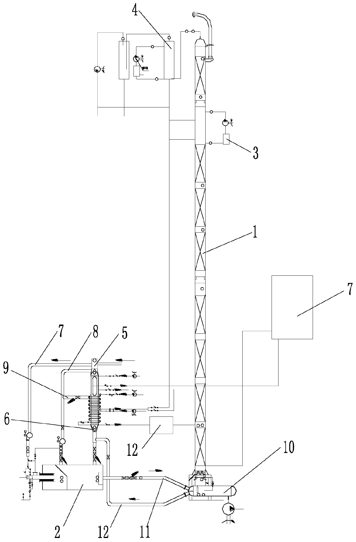
[0026] Such as Figure 3-Figure 4 , a purification device suitable for high-boiling point chemical raw materials, including a purification tower 1, a hot blast stove 2, a first condenser 3 is arranged on the upper part of the purification tower 1, a second condenser 4 is connected to the top of the purification tower 1, and the hot blast stove 2 utilizes waste heat The device is connected to the chimney 5, and the waste heat utilization device includes a flue 6. The air heating section 610, the steam heating section 620, the heat transfer oil heating section 630, and the raw material preheating heating section 640 are arranged on the flue 6 from top to bottom. The air heating section 610 is provided with a preheating air pipeline 611, the inlet of the preheating air pipeline 611 is fed with air, the outlet of the preheating air pipeline 611 is connected to the burner of the hot blast stove 2, and the steam heating section 620 is arranged with a steam pipeline 621 , the inlet of t


PUM


Abstract

The invention relates to a purification device suitable for high-boiling-point chemical raw materials, which comprises a purification tower and a hot-blast stove. The purification device, by fully utilizing the waste heat of the hot-blast stove, enables a combustion system, a waste heat boiler and a tower body to be naturally integrated. Overall distribution and centralized management of in-plantenergy are realized; therefore, the extracted fraction has higher purifty, and the height of the tower body is smaller. The temperature of a flue gas outlet can be controlled below 140 DEG C, adverseprocess conditions such as coking, carbon deposition, sublimation, atomization or easy formation of foam are avoided, and deep processing processes of rectification and distillation are innovated. Meanwhile, a cooling device is arranged outside the purification tower, so that the tower height is reduced, the cooling efficiency of the tower is improved, the fraction temperature before tower discharge is reduced and the heat efficiency of the tower is improved.

Description


Claims


Application Information

Patent Timeline
Owner ANSHAN XINUO HEAT ENERGY TECH
Why Eureka
Try Eureka