Feed hopper on mining iron removal equipment

A technology for feeding hoppers and equipment, applied in the field of mining machinery, can solve the problems affecting the adsorption of the magnet mechanism and the detachment of ferromagnetic impurities, and achieve the effect of preventing clogging

Inactive Publication Date: 2020-07-28
东莞市至简机电工程技术有限公司
View PDF0 Cites 0 Cited by
  • Summary
  • Abstract
  • Description
  • Claims
  • Application Information

AI Technical Summary

Problems solved by technology

The existing iron remover is generally transported by a conveyor belt, and the magnet mechanism is used to absorb and remove ferromagnetic impurities on the conveyor belt; but when the materials on the conveyor belt are piled up, the materials will bury the ferro

Method used


Image

  • Feed hopper on mining iron removal equipment
  • Feed hopper on mining iron removal equipment
  • Feed hopper on mining iron removal equipment

Examples


Embodiment

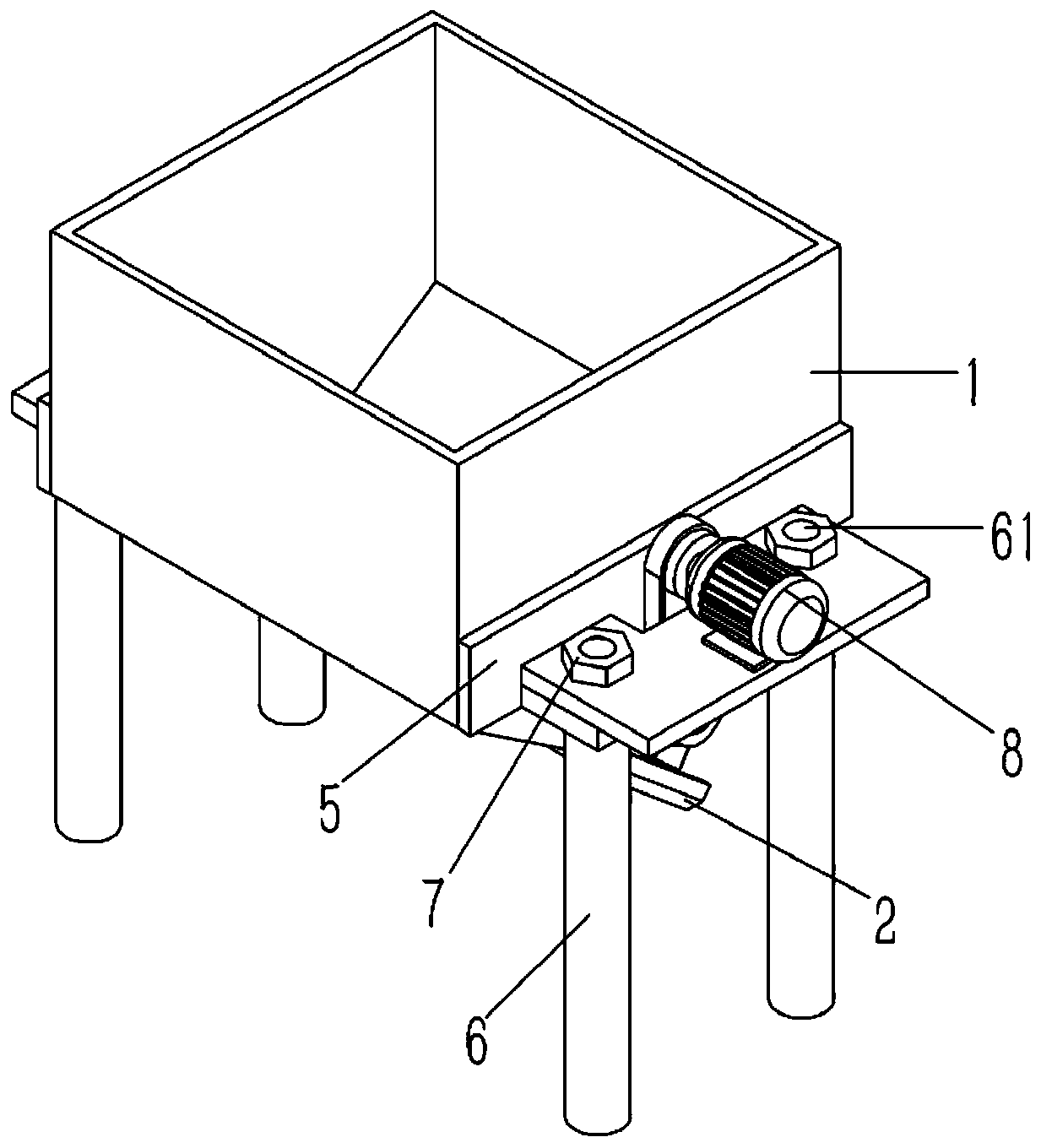
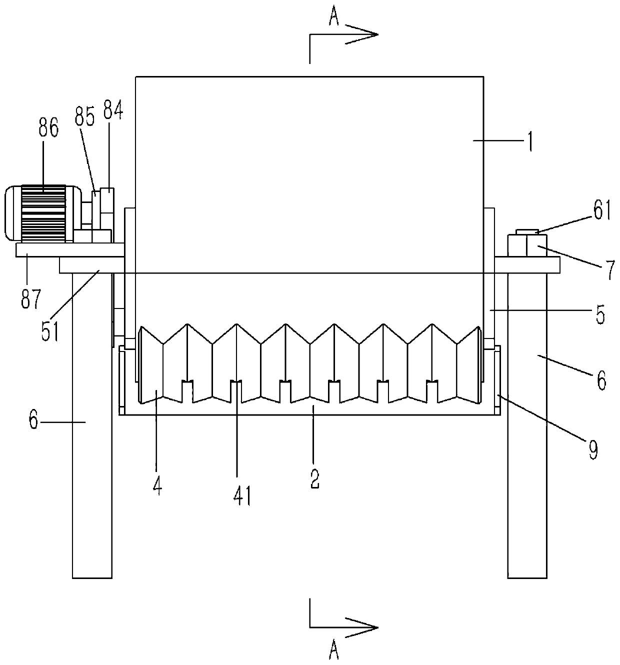
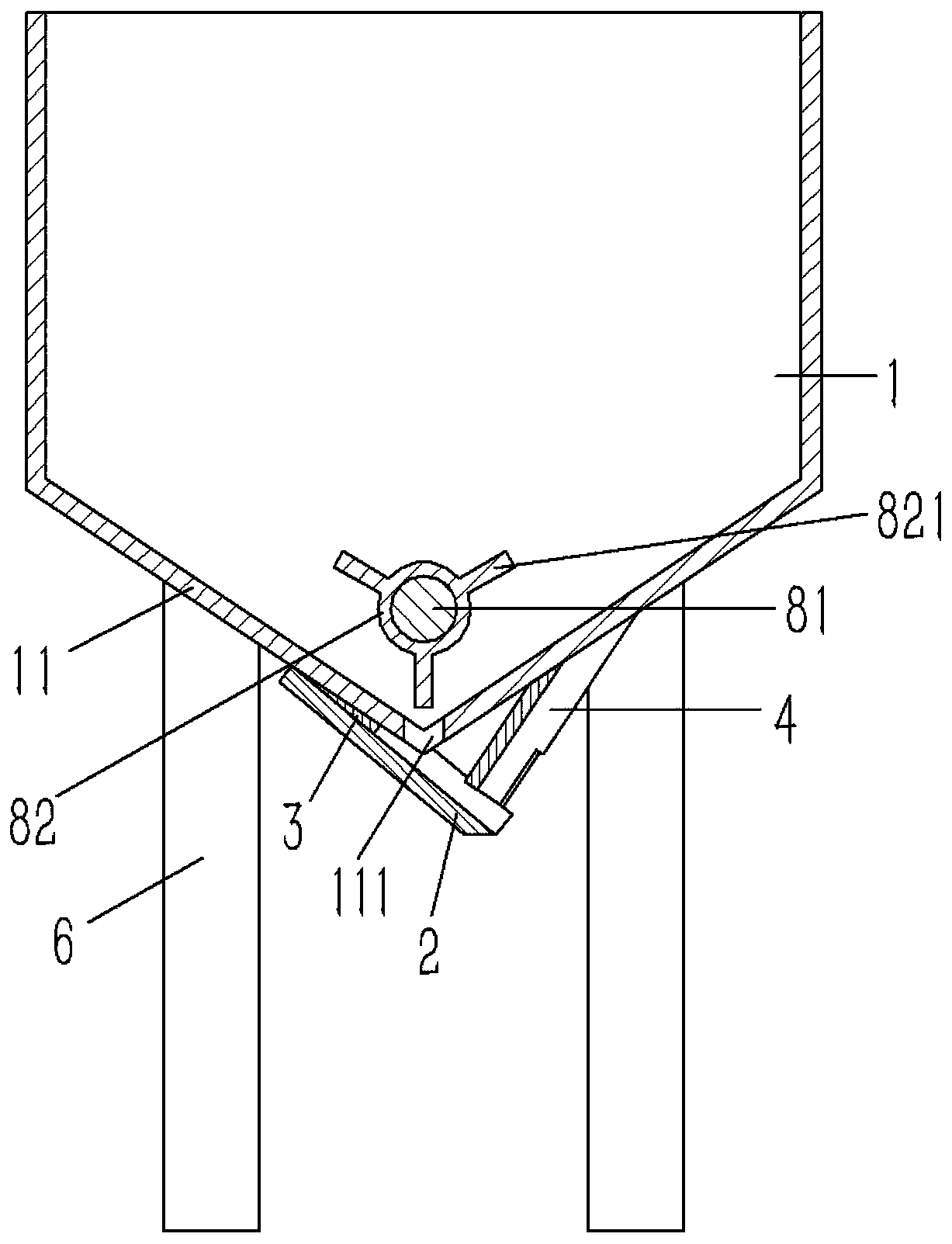
[0020] Example: see Figures 1 to 5 As shown, a feed hopper on a mining iron removal equipment includes a hopper 1, the lower end of the hopper 1 is formed with a tapered bucket body 11, and the lower end of the bucket body 11 is formed with several discharge ports 111; The rear end face of the deflector 2 is fixed with an inclined deflector 2, the front end of the deflector 2 is located directly below the front end of the bucket body 11, and a corrugated material retaining plate 4 is provided above the front of the deflector 2. There is a gap between the plate 4 and the deflector 2; the crest of the baffle plate 4 is facing the discharge port 111 on the bucket body 11, and the trough of the baffle plate 4 is distributed in the adjacent discharge port 111 Between, the upper end of the baffle plate 4 is fixed on the front end surface of the bucket body 11; the two side walls of the hopper 1 are fixed with a T-shaped support plate 5, and a number of horizontal support plates 51 are


PUM


Abstract

The invention discloses a feed hopper on mining iron removal equipment. The feed hopper comprises a hopper, wherein a tapered hopper body is shaped on the lower end of the hopper; a plurality of material outlets are shaped on the lower end of the hopper body; the rear end surface of the hopper body is fixedly provided with an inclined flow guiding plate; the front end of the flow guiding plate ispositioned just below the front end surface of the hopper body; a corrugated material blocking plate is arranged above the front part of the flow guiding plate; a gap is formed between the material blocking plate and the flow guiding plate; the wave crests of the material blocking plate just face the material outlets on the hopper body; the wave troughs of the material blocking plate are distributed between adjacent material outlets; the upper end of the material blocking plate is fixed on the front end surface of the hopper body; two side walls of the hopper are independently fixedly providedwith a T-shaped bracket plate; a plurality of horizontal supporting plates are shaped on each bracket plate; a stand column is abutted against the lower end surface of each supporting plate; and a stud is formed on the upper end of each stand column and penetrates through each bracket plate to be in screw joint with a nut.

Description


Claims


Application Information

Patent Timeline
Owner 东莞市至简机电工程技术有限公司
Why Eureka
Try Eureka