GPU resource scheduling method
A resource scheduling and resource technology, applied in the field of GPU resource scheduling, can solve the problem that GPU resources cannot be fully utilized, and achieve the effects of improving utilization efficiency, improving performance, and reducing costs
- Summary
- Abstract
- Description
- Claims
- Application Information
AI Technical Summary
Benefits of technology
Problems solved by technology
Method used
Image
Examples
Embodiment 1
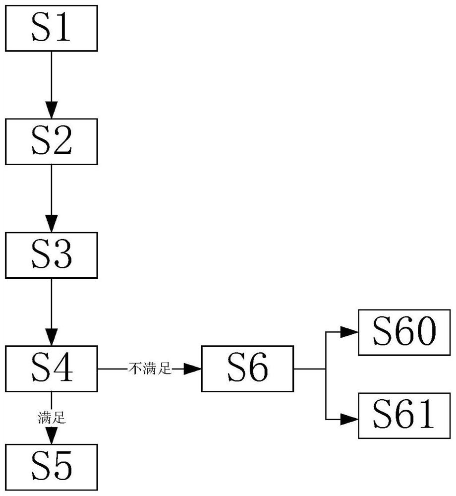
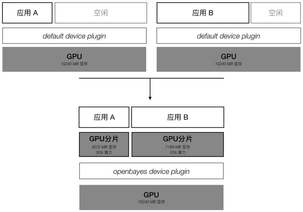
[0040] Such as figure 1 and 2 As shown, for an application that only needs one GPU, the resource allocation method is supported according to the required GPU memory and the required number of cores, instead of allocating a complete GPU to the application. The default GPU resource manager does not support the allocation of resources required by the application, but directly locks the entire GPU and allocates it to the required application.
[0041] A method for scheduling GPU resources, comprising steps:
[0042] S1. First, collect the basic information of the GPU from the cluster, and provide the gpu-usages interface, and enter step S2; in step S1, collect the basic information of the GPU, including the model of the GPU, the video memory, and the core of the GPU. It is convenient for the scheduler to obtain cluster GPU resource information.
[0043] S2. Create a GPU application, and send an application request to the Kubernetes scheduler, and enter step S3; in step S2, during
Embodiment 2
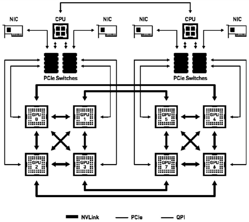
[0050] Such as figure 1 , 3 , 4, 5, and 6; for applications that require multiple GPUs: allocate according to the GPU group with the highest communication efficiency. The connection structure of GPUs in the machine is different, and the communication speed between GPUs will also be different. as attached image 3 As shown, the DGX-1 machine contains 8 GPUs, among which GPU0, GPU1, GPU2, GPU3, and GPU4 can be directly connected through NVLink, and its communication bandwidth can reach 40GB / s. The connection between GPU0 and GPU5, GPU6, and GPU7 needs to be completed through PCIe Switch and QPI, which greatly reduces the communication efficiency compared with NVLink. When allocating multiple GPUs to an application, the connection structure between the allocated multiple GPUs, also referred to as the GPU topology, should be considered. The topology structure between the GPUs can be obtained through the GPU driver, and the communication efficiency between the GPUs can be connec
Embodiment 3
[0063] Such as figure 1 , 2 , 3, 4, 5, and 6; for applications that require multiple GPUs: allocate according to the GPU group with the highest communication efficiency. The connection structure of GPUs in the machine is different, and the communication speed between GPUs will also be different. as attached image 3 As shown, the DGX-1 machine contains 8 GPUs, among which GPU0, GPU1, GPU2, GPU3, and GPU4 can be directly connected through NVLink, and its communication bandwidth can reach 40GB / s. The connection between GPU0 and GPU5, GPU6, and GPU7 needs to be completed through PCIe Switch and QPI, which greatly reduces the communication efficiency compared with NVLink. When allocating multiple GPUs to an application, the connection structure between the allocated multiple GPUs, also referred to as the GPU topology, should be considered. The topology structure between the GPUs can be obtained through the GPU driver, and the communication efficiency between the GPUs can be con
PUM
 Abstract
Description
Claims
Application Information
 - R&D Engineer
- R&D Manager
- IP Professional
- Industry Leading Data Capabilities
- Powerful AI technology
- Patent DNA Extraction
Browse by: Latest US Patents, China's latest patents, Technical Efficacy Thesaurus, Application Domain, Technology Topic.
© 2024 PatSnap. All rights reserved.Legal|Privacy policy|Modern Slavery Act Transparency Statement|Sitemap


