Test device and method for simulating stratum displacement caused by double-circle shield tunnel construction
A technology of tunnel construction and double-circle shield
Active Publication Date: 2020-12-11
CHONGQING JIAOTONG UNIVERSITY +1
View PDF7 Cites 0 Cited by
- Summary
- Abstract
- Description
- Claims
- Application Information
AI Technical Summary
Problems solved by technology
However, the water bag drainage method used in this test method cannot guarantee the stability of the cross-sectional shape of the tunnel during excavation.
Moreover, in order to realize the step-by-step excavation of the
Method used
View moreImage
Smart ImageViewing Examples

Examples
 PUM
 Abstract
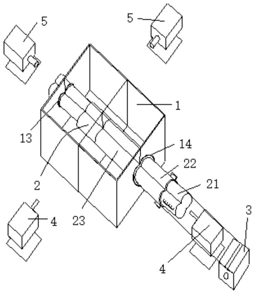
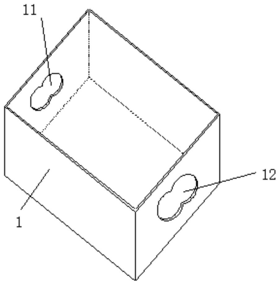
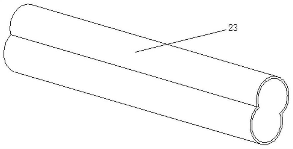
The invention relates to a test device and method for simulating stratum displacement caused by double-circle shield tunnel construction, and belongs to the field of civil engineering tests. The device comprises a transparent model box filled with transparent soil, a double-circle tunnel model, a tractor, laser emitters and cameras. The double-circle tunnel model horizontally penetrates through the transparent model box and comprises a transparent double-circle supporting column and a transparent double-circle pipe which are sleeved with each other and can slide relatively, and the transparentdouble-circle supporting column and the transparent double-circle pipe which are located in the transparent model box are embedded into transparent soil. The tractor is located outside the transparent model box and connected with the transparent double-circular pipe so as to discontinuously pull the transparent double-circular pipe to be horizontally drawn. The two laser emitters and the two cameras are arranged at the periphery of the transparent model box in a manner of corresponding to the transparent double-circular pipe, one laser emitter and one camera are arranged at the two sides of the drawing direction of the transparent double-circular pipe respectively, and the other laser emitter and the other camera are arranged at the two sides of the direction vertical to the drawing direction of the transparent double-circular pipe respectively. Operation is convenient, the structure is simple, and the simulation effect is visual and accurate.
Description
Login to view more Claims
Login to view more Application Information
Patent Timeline
 Owner CHONGQING JIAOTONG UNIVERSITY
- R&D Engineer
- R&D Manager
- IP Professional
Why Eureka
- Industry Leading Data Capabilities
- Powerful AI technology
- Patent DNA Extraction
Try Eureka
Browse by: Latest US Patents, China's latest patents, Technical Efficacy Thesaurus, Application Domain, Technology Topic.
© 2024 PatSnap. All rights reserved.Legal|Privacy policy|Modern Slavery Act Transparency Statement|Sitemap