Backlit radome

A technology of radar and radar waves, which is applied in the directions of antenna lighting/illumination, optical signal, radiation unit cover, etc., which can solve the problems of interfering with the normal passage of electromagnetic waves, measurement errors of external physical parameters, and useless auxiliary systems, etc.

Pending Publication Date: 2020-12-15
CO PLASTIC OMNIUM
View PDF1 Cites 0 Cited by
  • Summary
  • Abstract
  • Description
  • Claims
  • Application Information

AI Technical Summary

Benefits of technology

Inventors have developed various devices for vehicles' lights used in automobiles like those described earlier. These include detective lamps, LEDs, cameras, sensory systems, displays, etc., which help improve safety during driving operations. Additionally, they also aimed at adding special features onto their own equipment without affecting how well the car works. Overall, there was some improvement over existing designs when compared to older ones.

Problems solved by technology

Technologies described involve improving the performance of automotives without sacrificing their appearance when they meet high speeds during driving conditions like rain fogging. One solution involves adding cameras onto cars behind them along with lights placed under car windows. These cameras aim towards providing better visibility while still being able to see outside things clearly due to sunray reflections caused by water drops hitting against roadsides. Another approach uses special materials made up of conductors and transparency films to prevent reflection of radio signals. Additionally, there exist methods where radios have built-in sensitivity devices to measure various environmental factors including humidity levels, precipitation rates, salt crystal accumulation, and freezing point issues.

Method used


Image

  • Backlit radome
  • Backlit radome
  • Backlit radome

Examples


Embodiment Construction

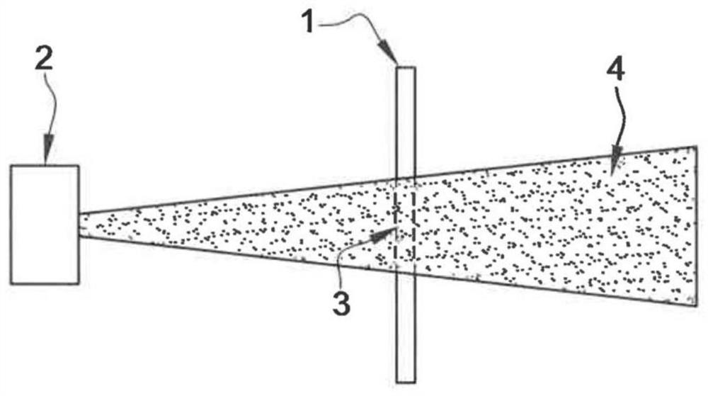
[0058] like figure 1 As shown, a protective device 1 according to the prior art, ie a radome, is intended to be arranged in front of a radar 2 . Radome 1 comprises at least one transmissive region 3 through which waves 4 of radar 2 can pass. The transmissive area 3 is formed of a material transparent to radar waves. The radome 1 can be fixed on the bumper of the motor vehicle, in front of the radar.

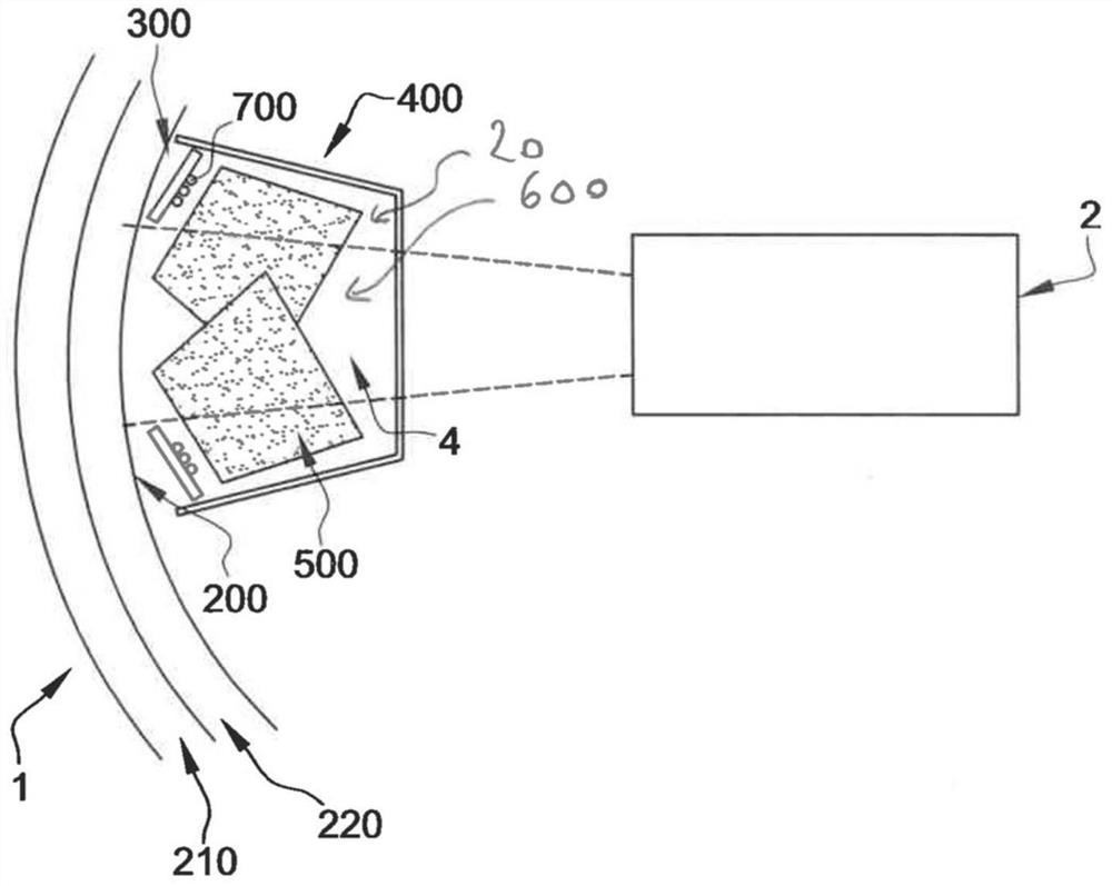
[0059] figure 2 A radome 1 according to one embodiment of the invention is shown. The protective device 1 of the motor vehicle radar 2 includes a body 200 formed of a material transparent to both radar waves 4 and light, two light sources 300 , and a light reflector 400 formed of a material transparent to the radar waves 4 . These elements are arranged such that the light beam 500 emitted by the light source 300 is reflected by the light reflector 400 towards the body 200 made of transparent material. The body 200 made of transparent material comprises two layers 210 , 220 .


PUM


Abstract

The invention relates to a motor vehicle radar (2) protection device (1) comprising the following elements: a body (200) formed from a material that is transparent to both radar waves (4) and light; alight source (300); a light reflector (400) formed of a material that is transparent to the radar waves (4); and an electrically conductive heating channel (12) arranged inside or at the surface of the body (200) made of transparent material. These elements are arranged such that a light beam (500) emitted by the light source (300) is reflected by the light reflector (400) towards the body (200)made of transparent material.

Description


Claims


Application Information

Patent Timeline
Owner CO PLASTIC OMNIUM
Why Eureka
Try Eureka